Среди пользователей персональных компьютеров вопрос, как зайти в Биос на Windows 7 становится все более злободневным. Связано это с тем, что изменилась схема этой операции. Если в ранних версиях этой операционной системы, чтобы выйти в Bios, требовалось всего лишь запустить комп и нажать одну кнопку, причем не существенно, какая именно ОС на компьютере установлена, то в новых версиях далеко не все так просто.
Поговорим подробнее о том, как данная процедура выполняется на Windows 7.
Содержание:
- Что такое Биос
- Как зайти в биос на Windows 7
- Способ № 1: стандартный
- Способ № 2: доступ к данным без предварительной перезагрузки компьютера
- Видео
Что такое Биос
Сначала немного терминов и теории. BIOS — (Basic Input/Output System) — базовая система, которая включает подготовку к запуску компьютера и его операционной системы. Иными словами, это небольшой набор мини-программ, которые вписаны в микросхему механизма на материнской плате. Наиболее основные и первые по запуску процессы на компьютере при подключении компьютера в сеть, которые и заводят всю эту машину, начинают работать именно здесь. Они обеспечивают взаимодействие механических устройств в компьютере.
Посмотрите, как войти в BIOS и выбрать загрузочное устройство.
В первую очередь при загрузке запускается первичная система, биос мониторит устройство на предмет работоспособности всех функций, а также осуществляет запуск операционной системы от того источника, который прописан в системных настройках. Это может быть:
- жесткий диск (чаще всего);
- флеш-носитель;
- CD и/или DVD-привод.
Биос в том числе отображает уровень нагрева комплектующих: процессора и материнской платы.

Как зайти в биос на Windows 7
Чтобы быстро входить в первичную систему BIOS на Windows 7 потребуется немедленно после включения машины нажать специальную клавишу на клавиатуре или комбинацию. Как правило, если все верно нажать, на экране возникает надпись при загрузке «Press DEL to enter SETUP» или «Press F1 to Run SETUP». Разница в комбинации клавиш может зависеть лишь от производителя материнской платы. В таком случае вид операционной системы роли не играет — будь то ХР или Windows 7.
При этом нужно учитывать, что каждый комп обладает каким-то своими индивидуальными особенностями. Компьютеры выполняют загрузку с разной скоростью: кто-то за пару секунд, кто-то за несколько минут. Вот чтобы не упустить тот момент, когда в БИОС можно зайти, рекомендуется нажимать на кнопку входа беспрерывно.
Итак, как было упомянуто выше, в зависимости от изготовителя вашего Bios на компьютере, клавиши для входа в него могут быть совершенно разными. Существуют различные таблицы, в которых упорядоченно представлены ОС и комбинации кнопок для выхода в их Биос. Они могут зависеть также от того, ПК у вас, ноутбук или нетбук.
Из этого видео вы узнаете, как установить Windows из Bios.
Если ознакомиться с этой таблицей, которая в интернете находится в свободном доступе, нет возможности или желания, то тогда следует учесть, что наиболее распространенными кнопками для входа в BIOS являются:
- Esc;
- Del;
- F2.
При их помощи — длительном нажатии или комбинации — и можно попасть в Bios. Если вы затрудняетесь понять, какая именно процедура поможет вам приступить к работе через первичную систему, то начать стоит именно с них.

Способ № 1: стандартный
Сперва определяемся с тем, BIOS какого производителя поставлен на вашем компьютере. На сегодняшний момент имеются три основные компании, занимающиеся разработкой подобных систем, следовательно, сочетание клавиш для входа в режим отладки, будет меняться исходя из того, какой у него разработчик.
Сразу после перезагрузки Винды информация об изготовителе высвечивается вверху экрана. Нередко там же, но внизу разработчики прописывают и желаемое сочетание кнопок.
Как только компьютер был перезагружен, можно приступать непосредственно к нажатию клавиши (или комбинации), причем ее или их следует не удерживать, а много раз нажимать с краткими интервалами.
Из видео вы узнаете, как зайти в BIOS на Windows 10.
Наиболее распространенными кнопками для того, чтобы выйти в bios на обычных компьютерах на базе операционной системы Windows 7, всегда являются:
- «F2»;
- «Delete»;
- «F1»;
- «Esc».
На некоторые модели ноутбуков нередко в качестве операционных клавиш для запуска первичной системы предлагают «F10» или, как вариант, комбинацию «Ctrl» + «Alt».
Существенным моментом является в том числе и тот факт, что в начальных версиях bios, после того, как вы смогли войти в режим отладки, манипулятор (мышь) не будет функционировать, поэтому всю навигацию надо будет осуществлять с использованием клавиши «Ввода» (enter) и стрелок клавиатуры. В отдельных особенно «допотопных» версиях для этих целей могут использоваться клавиши «Page Down» и «Page Up».
Теперь, когда вам удалось войти в режим отладки после перезагрузки операционной системы, вы имеете возможность выбирать нужный раздел для ознакомления с необходимой информацией или для внесения требуемых изменений в настройках пк. Любой из пунктов, опять же отвечает за множество характеристик. Но об этом мы поговорим в следующий раз.

Способ № 2: доступ к данным без предварительной перезагрузки компьютера
Если по каким-то причинам не получилось определить, биос какого именно производителя поставлен на вашем ПК, в связи с чем войти в режим отладки оказывается невозможным, то имеется способ определить, какая версия базовой ОС на текущий момент установлена на вашей рабочей цифровой машине без перезагрузки ПК.

Нередко эти сведения присутствуют в инструкции, которая поставляется в комплекте с компьютером. Однако это не вариант, если агрегат приобретался давно или это вообще собранная вручную машина. Тогда выручит такая процедура:
- войти в «Диспетчер задач»,
- открыть «Новая задача»,
- далее — «Файл».
Нажимаем «Открыть» и вводим команду «msinfo32», после чего подтверждаем через клавишу «Ok». Равным образом можно просто ввести ту же команду «msinfo32» в поисковую строку, которая обычно расположена в меню «Пуск», после чего нажать «Ввод». Откроется окно, и на экране высветится исчерпывающая информация об операционной системе: ее текущее состояние и вся необходимая информация.Теперь, владея данной информацией, вы сможете с легкостью выходить в режим отладки, подобрать требуемое сочетание клавиш.
Видео
Посмотрите, как можно зайти в BIOS на комптьютере или ноутбуке.

Что такое биос простыми словами. Как зайти на ноутбуке и компьютере
Опубликовано 01.02.2022
Содержание:
- 1 Что такое BIOS
- 1.1 UEFI (BIOS) — что это
- 2 Что делает BIOS
- 2.1 Как работает программа
- 3 Как зайти в BIOS
- 3.1 Клавиши (или их сочетания) для входа в BIOS
- 4 Где на компьютере и ноутбуке находится «БИОС»
- 5 Виды BIOS
- 6 Зачем обновлять BIOS
- 6.1 Как на своем компьютере узнать версию «БИОС»
- 7 Заключение
BIOS — сокращение Basic Input — Output System, «Базовая система ввода — вывода». Так называется важнейшая программа компьютера, запускаемая первоначально.«БИОС» тестирует и активирует все компоненты, после чего передает контроль операционной системе. Настройки BIOS влияют на способ загрузки, ход работы и взаимодействия устройств. В статье мы расскажем, что такое «БИОС», для чего предназначен и как в него зайти.

UEFI (BIOS) — что это
В основном новые модели компьютеров оснащают UEFI. Говоря простыми словами, это усовершенствованный BIOS. Unified Extensible Firmware Interface означает «унифицированный расширяемый интерфейс прошивки». Среди преимуществ программы (по сравнению с «БИОС»):
- поддержка жестких дисков более значительного объема;
- управление с помощью мышки;
- мультиязычное меню;
- ускоренная загрузка;
- встроенные драйверы основных компонентов;
- более удобный графический интерфейс.
В зависимости от версии программы пользователь может до загрузки ОС выйти в сеть, воспроизвести информацию с внешних носителей, провести диагностику ПК, получить доступ к менеджерам файлов и остальным полезным инструментам. Но при этом посредством UEFI изготовители железа способны ограничить юзера в выборе ОС или манипуляций с ней.
Что делает BIOS
Основная функция BIOS (или UEFI) — аппаратная настройка ПК. Работая в меню программы, пользователь может:
- получать данные о главных компонентах ПК — наименования моделей, серийные номера и т. д.;
- отключать некоторые неиспользуемые устройства (например, чтобы сэкономить заряд батарейки ноутбука);
- получать информацию о параметрах работы компонентов компьютера (частота, температура, скорость, используемые технологии);
- изменять характеристики работы устройств ПК, включать и отключать применяемые технологии;
- выставлять системное время;
- устанавливать приоритет загрузки.
Возможности, которые предоставляет BIOS (UEFI), зависят от версии программы и характеристик компонентов ПК. Для получения максимального эффекта пользователю необходимо детально изучить настройки и продумать, как с их помощью оптимизировать работу компьютера.
Как работает программа
Пользователь нажимает кнопку включения компьютера. ПК в режиме самотестирования обращается к «БИОС» для получения дальнейших указаний. Если проверка «жизненно важных» устройств дала положительный результат, то BIOS ищет доступный загрузчик ОС, после чего передает операционной системе управление компьютером. Все, на этом миссия программы завершена, и заново она запускается только при следующей загрузке ПК.
Как зайти в BIOS
Чтобы зайти BIOS (UEFI), нужно «поймать» короткий момент между включением компьютера и запуском ОС и в этот временной интервал нажать особую клавишу. Чтобы исключить неудачу, эту кнопку нужно удерживать либо периодически ее нажимать (раз—два в секунду). Если войти все же не получилось, отправляем компьютер на перезагрузку и снова «ловим момент».
Чаще всего, чтобы зайти в «БИОС», нажимают кнопку Del (Delete) или F2, а также другие клавиши (либо их сочетание). Компьютер во время самотестирования на первоначальном экране дает подсказку, что именно нужно нажать. Это может выглядеть как Press F2 to enter setup, Esc — setup и т. д. Это означает, что в первом случае нужно нажимать F2, во втором — Esc.
Меню разных версий BIOS и UEFI существенно различаются. Но обычно это разделы, содержащие конкретные характеристики работы ПК либо ноутбука. У большинства параметров можно менять значения. Управление настройками достаточно просто (в правой части экрана есть подсказки):
- Перейти между разделами: «→» и «←».
- Выбрать определенный параметр в нужном разделе: «↑» и «↓».
- Изменить выбранную характеристику: Enter, «+», «-» или набор нужных числовых значений.
- Сохранить изменения и загрузить ОС с их учетом: F10, потом Enter.
- Выйти без изменений: Esc, потом Enter.
Для работы в UEFI возможно использовать мышь.
Клавиши (или их сочетания) для входа в BIOS
Каждый производитель предоставляет пользователям доступ в «БИОС» с помощью различных клавиш (либо их сочетаний). В таблице ниже мы перечислили основные команды на наиболее популярных моделях компьютеров и ноутбуков. Если у вас есть, чем дополнить имеющуюся информацию, напишите нам в специальной форме внизу статьи.
| Модель | Стандартный вход в BIOS (нажимать клавиши сразу после включения компьютера) | Особенности |
|---|---|---|
| Acer: Aspire, Predator, Spin, Swift, Extensa, Ferrari, Power, Altos, TravelMate, Veriton |
Del или F2 | 1. Acer Veriton L480G — F12. 2. Сервер Acer Altos 600 — Ctrl + Alt + Esc и F1 для дополнительных параметров. 3. Старые компьютеры — F1 или Ctrl + Alt + Esc |
| Asus: B-Series, ROG-Series, Q-Series, VivoBook, Zen AiO, ZenBook |
F2. Возможно, придется нажимать несколько раз | 1. Некоторые ноутбуки — Del, Esc, F10. 2. Старые компьютеры — удерживать Esc, пока не откроется экран выбора загрузочного устройства, затем выбрать Enter Setup |
| Compaq: Presario, Prolinea, Deskpro, Systempro, Portable |
F10, пока мигает курсор в верхнем правом углу экрана | Старые компьютеры — F1, F2, F10, Del |
| Dell: XPS, Dimension, Inspiron, Latitude, OptiPlex, Precision, Alienware, Vostro |
Нажимать F2 каждые несколько секунд при появлении логотипа производителя до выхода сообщения «Вход в настройку» | 1. Старые ПК и ноутбуки — Ctrl + Alt + Enter или Del. 2. Старые ноутбуки — Fn + Esc или Fn + F1 |
| Emachines: eMonster, eTower, eOne, серия S, серия T |
Tab или Del до появления логотипа производителя | Некоторые модели — F2 |
| EVGA: SC17, SC15 |
Нажимать Del несколько раз во время загрузки ноутбука | |
| Fujitsu: LifeBook, Esprimo, Amilo, Tablet, DeskPower, Celsius |
Нажать F2 сразу при появлении логотипа производителя | |
| Gateway: DX, FX, LT, NV, NE, One, GM, GT, GX, SX, Profile, Astro |
Несколько раз нажать F1 или F2. Возможно, клавишу будет нужно нажать и удерживать | |
| Hewlett-Packard (HP): Pavilion, EliteBook, ProBook, Pro, OMEN, ENVY, TouchSmart, Vectra, OmniBook, Tablet, Stream, ZBook |
F1, F10 или F11 | 1. Планшетные ПК — F10 или F12. 2. Некоторые модели — F2, Esc или Esc + F10. |
| IBM: PC, XT, AT |
F1 | Старые компьютеры и некоторые ноутбуки — F2 |
| Lenovo (ранее IBM): ThinkPad, IdeaPad, Yoga, Legion, H535, 3000 Series, N Series, ThinkCentre, ThinkStation |
F1 или F2 | 1. Некоторые модели сбоку располагают кнопкой Novo (рядом с кнопкой питания), которую необходимо нажать (или нажать и удерживать). Возможно, нужно будет войти в BIOS Setup после появления экрана. 2. F12. 3. Старые модели — Ctrl + Alt + F3, Ctrl + Alt + Ins или Fn + F1. |
| Micron (MPC Computers): ClientPro, TransPort |
F1, F2, Del | |
| NEC: PowerMate, Versa, W-Series |
F2 | |
| Packard Bell: 8900 Series, 9000 Series, Pulsar, Platinum, EasyNote, iMedia, Ixtreme |
F1, F2 или Del | |
| Samsung: Odyssey, Notebook 5/7/9, ArtPC PULSE, Series ‘x’ laptops |
F2 (возможно, нужно будет нажать и удерживать) | |
| Sharp: Notebook Laptops, Actius UltraLite |
F2 | Очень старые компьютеры требуют установочный диагностический диск |
| Shuttle: Glamor G-Series, D’vo, Prima P2-Series, Workstation, XPC, Surveillance |
F2, Del | |
| Sony: VAIO, PCG-Series, VGN-Series |
F1, F2 или F3 | |
| Toshiba: Portégé, Satellite, Tecra, Equium |
F1, Esc | Toshiba Equium — F12 |
| ARI / ALR / AST | Ctrl + Alt + Esc, Ctrl + Alt + Del | |
| Cybermax | Esc | |
| Tandon | Ctrl + Shift + Esc | |
| Medion | Del |
Если не получается зайти в BIOS с помощью команд вышеуказанной таблицы, попробуйте выполнить вход на основе информации о производителе базовой системы. Наименование фирмы можно найти на микросхеме, расположенной на материнской плате или первоначальном экране компьютера сразу после включения. Также, чтобы определить производителя BIOS, откройте информацию о системе: в меню «Выполнить» (win+r) наберите msinfo32, подтвердите OK и найдите нужные данные.
| Производитель BIOS | Стандартный вход в BIOS (нажимать клавиши сразу после включения компьютера) | Особенности |
|---|---|---|
| AMI (American Megatrends): AMIBIOS, AMI BIOS |
Del | Устаревшие материнские платы — F1, F2 |
| Award Software (Phoenix Technologies) AwardBIOS, Award BIOS |
Del | Устаревшие материнские платы — Ctrl + Alt + Esc |
| DTK (Datatech Enterprises) DTK BIOS |
Esc | |
| Insyde Software Insyde BIOS |
F2 | Если во время самотестирования компьютер издает более одного звукового сигнала или не пищит вообще, сообщая об ошибке, необходимо нажать F1 (F2 в этом случае устраняет ошибку и не дает запустить «БИОС» |
| Microid Research MR BIOS |
F1 | |
| Phoenix Technologies Phoenix BIOS, Phoenix-Award BIOS |
Del | Устаревшие системы — Ctrl + Alt + Esc, Ctrl + Alt + Ins, Ctrl + Alt + S |
Если никак не получается осуществить вход в «БИОС» или определить производителя, то есть еще несколько команд, которыми можно попробовать вызвать меню настроек:
- F3
- F4
- F10
- F12
- Tab
- Ctrl + Insert
- Ctrl + Alt + Del
- Ctrl + Alt + F3
- Ctrl + Alt + Shift + Del
- Ctrl + Shift + Esc
- Fn + [любая функциональная клавиша «F»] (на отдельных моделях ноутбуков).
Где на компьютере и ноутбуке находится «БИОС»
Программа размещена в особой микросхеме на матплате, которая называется ROM BIOS или «микросхема ПЗУ». Поэтому компьютер всегда имеет доступ к «БИОС» еще до запуска ОС. Специальную микросхему питает плоская батарейка типа CR2032. Если ее вынуть либо разрядить, то из BIOS удалятся пользовательские изменения, и программа вернется к базовым настройкам. Но, если ее перепрошить (заменить на другую версию), то после обесточивания правки останутся. Это хороший вариант для решения проблем совместимости компонентов или устранения некоторых недочетов, но такие действия способен выполнить лишь профессионал. Иначе в результате некорректной деятельности пользователь может столкнуться с очень неприятными последствиями — вплоть до покупки новой материнской платы.
Это BIOS на ПК:

Это на ноутбуке:

Виды BIOS
Каждый производитель вносит свои правки в BIOS, но по существу все вариации обладают одинаковым функционалом. На сегодня существует 4 популярные версии:
- AMI BIOS. Применялся на старых устройствах. Обладал серо-синим интерфейсом.
- Intel BIOS. Вариация AMI, переделанная организацией Intel.
- Phoenix BIOS (Award). Понятная программа, используется и сейчас на множестве моделей ноутбуков и ПК.
- UEFI. Интереснейшая многофункциональная версия. Возможно, новые матплаты будут выпускать с UEFI.
Зачем обновлять BIOS
В некоторых случаях «БИОС» необходимо обновлять (доверьте это дело профессионалам):
- При несовместимости компонентов. Например, устаревшая материнская плата отказывается работать с современной высокочастотной оперативной памятью. В результате BIOS не понимает, как взаимодействовать с устройством, компьютер отказывается работать, пищит и выдает ошибки.
- При наличии критических ошибок в «БИОС», нуждающихся в срочном исправлении;
- При внесении производителями доработок, улучшающих функционирование компьютера.
Перед обновлением нужно детально изучить изменения и решить, актуальны ли они для конкретного ПК. Если компьютер работает без нареканий, то не стоит вмешиваться и в работу BIOS, иначе возможно испортить то, что хорошо функционирует.
Как на своем компьютере узнать версию «БИОС»
Прежде чем обновлять BIOS, нужно узнать, что за вариация инсталлирована на ПК. Опишем основные способы:
- Информация на экране, появляющемся сразу при включении компьютера.

- Данные из утилиты «Выполнить». Нажимаем win+r, вводим msinfo32. Информация находится в строке «Версия BIOS».
- Сведения из сторонних программ, например, CPU-Z, AIDA64.
Обновления BIOS производители материнских плат либо ноутбуков размещают на своих официальных сайтах.
Заключение
BIOS тестирует важнейшие компоненты компьютера, прежде чем запустить операционную систему. От работы этой программы зависит работа и взаимодействие устройств, параметры работы которых можно изменять, если поймать момент между включением ПК и запуском ОС. Иногда «БИОС» необходимо обновлять, но лучше всего доверить эту работу профессионалам, иначе правки могут дать обратный эффект.
Специалисты компании «АйТи Спектр» оказывают профессиональную ИТ-поддержку для организаций и предпринимателей Москвы и МО. Обеспечим бесперебойную работу компьютерной техники и ваш бизнес будет функционировать в штатном режиме 365 дней в году.
This article is about the BIOS as found in personal computers. For other uses, see Bios (disambiguation).

A pair of AMD BIOS chips for a Dell 310 computer from the 1980s. The bottom one shows the distinct window of an EPROM chip.
In computing, BIOS (, BY-oss, -ohss; Basic Input/Output System, also known as the System BIOS, ROM BIOS, BIOS ROM or PC BIOS) is firmware used to provide runtime services for operating systems and programs and to perform hardware initialization during the booting process (power-on startup).[1] The BIOS firmware comes pre-installed on an IBM PC or IBM PC compatible’s system board and exists in some UEFI-based systems to maintain compatibility with operating systems that do not support UEFI native operation.[2][3] The name originates from the Basic Input/Output System used in the CP/M operating system in 1975.[4][5] The BIOS originally proprietary to the IBM PC has been reverse engineered by some companies (such as Phoenix Technologies) looking to create compatible systems. The interface of that original system serves as a de facto standard.
The BIOS in modern PCs initializes and tests the system hardware components (Power-on self-test), and loads a boot loader from a mass storage device which then initializes a kernel. In the era of DOS, the BIOS provided BIOS interrupt calls for the keyboard, display, storage, and other input/output (I/O) devices that standardized an interface to application programs and the operating system. More recent operating systems do not use the BIOS interrupt calls after startup.[6]
Most BIOS implementations are specifically designed to work with a particular computer or motherboard model, by interfacing with various devices especially system chipset. Originally, BIOS firmware was stored in a ROM chip on the PC motherboard. In later computer systems, the BIOS contents are stored on flash memory so it can be rewritten without removing the chip from the motherboard. This allows easy, end-user updates to the BIOS firmware so new features can be added or bugs can be fixed, but it also creates a possibility for the computer to become infected with BIOS rootkits. Furthermore, a BIOS upgrade that fails could brick the motherboard. The last version of Microsoft Windows running on PCs which uses BIOS firmware is Windows 10.
Unified Extensible Firmware Interface (UEFI) is a successor to the legacy PC BIOS, aiming to address its technical limitations.[7]
History[edit]
/* C P / M   B A S I C   I / O    S Y S T E M    (B I O S)
                    COPYRIGHT (C) GARY A. KILDALL
                             JUNE, 1975 */
[…]
/*  B A S I C   D I S K    O P E R A T I N G   S Y S T E M  (B D O S)
                    COPYRIGHT (C) GARY A. KILDALL
                            JUNE, 1975 */
The term BIOS (Basic Input/Output System) was created by Gary Kildall[8][9] and first appeared in the CP/M operating system in 1975,[4][5][9][10][11][12] describing the machine-specific part of CP/M loaded during boot time that interfaces directly with the hardware.[5] (A CP/M machine usually has only a simple boot loader in its ROM.)
Versions of MS-DOS, PC DOS or DR-DOS contain a file called variously «IO.SYS», «IBMBIO.COM», «IBMBIO.SYS», or «DRBIOS.SYS»; this file is known as the «DOS BIOS» (also known as the «DOS I/O System») and contains the lower-level hardware-specific part of the operating system. Together with the underlying hardware-specific but operating system-independent «System BIOS», which resides in ROM, it represents the analogue to the «CP/M BIOS».
The BIOS originally proprietary to the IBM PC has been reverse engineered by some companies (such as Phoenix Technologies) looking to create compatible systems.
With the introduction of PS/2 machines, IBM divided the System BIOS into real- and protected-mode portions. The real-mode portion was meant to provide backward compatibility with existing operating systems such as DOS, and therefore was named «CBIOS» (for «Compatibility BIOS»), whereas the «ABIOS» (for «Advanced BIOS») provided new interfaces specifically suited for multitasking operating systems such as OS/2.[13]
User interface[edit]
The BIOS of the original IBM PC and XT had no interactive user interface. Error codes or messages were displayed on the screen, or coded series of sounds were generated to signal errors when the power-on self-test (POST) had not proceeded to the point of successfully initializing a video display adapter. Options on the IBM PC and XT were set by switches and jumpers on the main board and on expansion cards. Starting around the mid-1990s, it became typical for the BIOS ROM to include a «BIOS configuration utility» (BCU[14]) or «BIOS setup utility», accessed at system power-up by a particular key sequence. This program allowed the user to set system configuration options, of the type formerly set using DIP switches, through an interactive menu system controlled through the keyboard. In the interim period, IBM-compatible PCs—including the IBM AT—held configuration settings in battery-backed RAM and used a bootable configuration program on floppy disk, not in the ROM, to set the configuration options contained in this memory. The floppy disk was supplied with the computer, and if it was lost the system settings could not be changed. The same applied in general to computers with an EISA bus, for which the configuration program was called an EISA Configuration Utility (ECU).
A modern Wintel-compatible computer provides a setup routine essentially unchanged in nature from the ROM-resident BIOS setup utilities of the late 1990s; the user can configure hardware options using the keyboard and video display. The modern Wintel machine may store the BIOS configuration settings in flash ROM, perhaps the same flash ROM that holds the BIOS itself.
Operation[edit]
System startup[edit]
Early Intel processors started at physical address 000FFFF0h. Systems with later processors provide logic to start running the BIOS from the system ROM.
[15]
If the system has just been powered up or the reset button was pressed («cold boot»), the full power-on self-test (POST) is run. If Ctrl+Alt+Delete was pressed («warm boot»), a special flag value stored in nonvolatile BIOS memory («CMOS») tested by the BIOS allows bypass of the lengthy POST and memory detection.
The POST identifies, tests and initializes system devices such as the CPU, chipset, RAM, motherboard, video card, keyboard, mouse, hard disk drive, optical disc drive and other hardware, including integrated peripherals.
Early IBM PCs had a routine in the POST that would download a program into RAM through the keyboard port and run it.[16][17] This feature was intended for factory test or diagnostic purposes.
Boot process[edit]

After the option ROM scan is completed and all detected ROM modules with valid checksums have been called, or immediately after POST in a BIOS version that does not scan for option ROMs, the BIOS calls INT 19h to start boot processing. Post-boot, programs loaded can also call INT 19h to reboot the system, but they must be careful to disable interrupts and other asynchronous hardware processes that may interfere with the BIOS rebooting process, or else the system may hang or crash while it is rebooting.
When INT 19h is called, the BIOS attempts to locate boot loader software on a «boot device», such as a hard disk, a floppy disk, CD, or DVD. It loads and executes the first boot software it finds, giving it control of the PC.[18]
The BIOS uses the boot devices set in Nonvolatile BIOS memory (CMOS), or, in the earliest PCs, DIP switches. The BIOS checks each device in order to see if it is bootable by attempting to load the first sector (boot sector). If the sector cannot be read, the BIOS proceeds to the next device. If the sector is read successfully, some BIOSes will also check for the boot sector signature 0x55 0xAA in the last two bytes of the sector (which is 512 bytes long), before accepting a boot sector and considering the device bootable.[nb 1]
When a bootable device is found, the BIOS transfers control to the loaded sector. The BIOS does not interpret the contents of the boot sector other than to possibly check for the boot sector signature in the last two bytes. Interpretation of data structures like partition tables and BIOS Parameter Blocks is done by the boot program in the boot sector itself or by other programs loaded through the boot process.
A non-disk device such as a network adapter attempts booting by a procedure that is defined by its option ROM or the equivalent integrated into the motherboard BIOS ROM. As such, option ROMs may also influence or supplant the boot process defined by the motherboard BIOS ROM.
With the El Torito optical media boot standard, the optical drive actually emulates a 3.5″ high-density floppy disk to the BIOS for boot purposes. Reading the «first sector» of a CD-ROM or DVD-ROM is not a simply defined operation like it is on a floppy disk or a hard disk. Furthermore, the complexity of the medium makes it difficult to write a useful boot program in one sector. The bootable virtual floppy disk can contain software that provides access to the optical medium in its native format.
Boot priority[edit]
The user can select the boot priority implemented by the BIOS. For example, most computers have a hard disk that is bootable, but sometimes there is a removable-media drive that has higher boot priority, so the user can cause a removable disk to be booted.
In most modern BIOSes, the boot priority order can be configured by the user. In older BIOSes, limited boot priority options are selectable; in the earliest BIOSes, a fixed priority scheme was implemented, with floppy disk drives first, fixed disks (i.e. hard disks) second, and typically no other boot devices supported, subject to modification of these rules by installed option ROMs. The BIOS in an early PC also usually would only boot from the first floppy disk drive or the first hard disk drive, even if there were two drives installed.
Boot failure[edit]
On the original IBM PC and XT, if no bootable disk was found, ROM BASIC was started by calling INT 18h. Since few programs used BASIC in ROM, clone PC makers left it out; then a computer that failed to boot from a disk would display «No ROM BASIC» and halt (in response to INT 18h).
Later computers would display a message like «No bootable disk found»; some would prompt for a disk to be inserted and a key to be pressed to retry the boot process. A modern BIOS may display nothing or may automatically enter the BIOS configuration utility when the boot process fails.
Boot environment[edit]
The environment for the boot program is very simple: the CPU is in real mode and the general-purpose and segment registers are undefined, except SS, SP, CS, and DL. CS:IP always points to physical address 0x07C00. What values CS and IP actually have is not well defined. Some BIOSes use a CS:IP of 0x0000:0x7C00 while others may use 0x07C0:0x0000.[19] Because boot programs are always loaded at this fixed address, there is no need for a boot program to be relocatable. DL may contain the drive number, as used with INT 13h, of the boot device. SS:SP points to a valid stack that is presumably large enough to support hardware interrupts, but otherwise SS and SP are undefined. (A stack must be already set up in order for interrupts to be serviced, and interrupts must be enabled in order for the system timer-tick interrupt, which BIOS always uses at least to maintain the time-of-day count and which it initializes during POST, to be active and for the keyboard to work. The keyboard works even if the BIOS keyboard service is not called; keystrokes are received and placed in the 15-character type-ahead buffer maintained by BIOS.) The boot program must set up its own stack, because the size of the stack set up by BIOS is unknown and its location is likewise variable; although the boot program can investigate the default stack by examining SS:SP, it is easier and shorter to just unconditionally set up a new stack.[20]
At boot time, all BIOS services are available, and the memory below address 0x00400 contains the interrupt vector table. BIOS POST has initialized the system timers, interrupt controller(s), DMA controller(s), and other motherboard/chipset hardware as necessary to bring all BIOS services to ready status. DRAM refresh for all system DRAM in conventional memory and extended memory, but not necessarily expanded memory, has been set up and is running. The interrupt vectors corresponding to the BIOS interrupts have been set to point at the appropriate entry points in the BIOS, hardware interrupt vectors for devices initialized by the BIOS have been set to point to the BIOS-provided ISRs, and some other interrupts, including ones that BIOS generates for programs to hook, have been set to a default dummy ISR that immediately returns. The BIOS maintains a reserved block of system RAM at addresses 0x00400–0x004FF with various parameters initialized during the POST. All memory at and above address 0x00500 can be used by the boot program; it may even overwrite itself.[21][22]
Extensions (option ROMs)[edit]
Peripheral cards such as hard disk drive host bus adapters and video cards have their own firmware, and BIOS extension option ROM may be a part of the expansion card firmware, which provide additional functionality to BIOS. Code in option ROMs runs before the BIOS boots the operating system from mass storage. These ROMs typically test and initialize hardware, add new BIOS services, or replace existing BIOS services with their own services. For example, a SCSI controller usually has a BIOS extension ROM that adds support for hard drives connected through that controller. An extension ROM could in principle contain operating system, or it could implement an entirely different boot process such as network booting. Operation of an IBM-compatible computer system can be completely changed by removing or inserting an adapter card (or a ROM chip) that contains a BIOS extension ROM.
The motherboard BIOS typically contains code for initializing and bootstrapping integrated display and integrated storage. In addition, plug-in adapter cards such as SCSI, RAID, network interface cards, and video cards often include their own BIOS (e.g. Video BIOS), complementing or replacing the system BIOS code for the given component. Even devices built into the motherboard can behave in this way; their option ROMs can be a part of the motherboard BIOS.
An add-in card requires an option ROM if the card is not supported by the motherboard BIOS and the card needs to be initialized or made accessible through BIOS services before the operating system can be loaded (usually this means it is required in the boot process). An additional advantage of ROM on some early PC systems (notably including the IBM PCjr) was that ROM was faster than main system RAM. (On modern systems, the case is very much the reverse of this, and BIOS ROM code is usually copied («shadowed») into RAM so it will run faster.)
Boot procedure[edit]
If an expansion ROM wishes to change the way the system boots (such as from a network device or a SCSI adapter) in a cooperative way, it can use the BIOS Boot Specification (BBS) API to register its ability to do so. Once the expansion ROMs have registered using the BBS APIs, the user can select among the available boot options from within the BIOS’s user interface. This is why most BBS compliant PC BIOS implementations will not allow the user to enter the BIOS’s user interface until the expansion ROMs have finished executing and registering themselves with the BBS API.[citation needed]
Also, if an expansion ROM wishes to change the way the system boots unilaterally, it can simply hook INT 19h or other interrupts normally called from interrupt 19h, such as INT 13h, the BIOS disk service, to intercept the BIOS boot process. Then it can replace the BIOS boot process with one of its own, or it can merely modify the boot sequence by inserting its own boot actions into it, by preventing the BIOS from detecting certain devices as bootable, or both. Before the BIOS Boot Specification was promulgated, this was the only way for expansion ROMs to implement boot capability for devices not supported for booting by the native BIOS of the motherboard.[citation needed]
Initialization[edit]
After the motherboard BIOS completes its POST, most BIOS versions search for option ROM modules, also called BIOS extension ROMs, and execute them. The motherboard BIOS scans for extension ROMs in a portion of the «upper memory area» (the part of the x86 real-mode address space at and above address 0xA0000) and runs each ROM found, in order. To discover memory-mapped option ROMs, a BIOS implementation scans the real-mode address space from 0x0C0000 to 0x0F0000 on 2 KB (2,048 bytes) boundaries, looking for a two-byte ROM signature: 0x55 followed by 0xAA. In a valid expansion ROM, this signature is followed by a single byte indicating the number of 512-byte blocks the expansion ROM occupies in real memory, and the next byte is the option ROM’s entry point (also known as its «entry offset»). If the ROM has a valid checksum, the BIOS transfers control to the entry address, which in a normal BIOS extension ROM should be the beginning of the extension’s initialization routine.
At this point, the extension ROM code takes over, typically testing and initializing the hardware it controls and registering interrupt vectors for use by post-boot applications. It may use BIOS services (including those provided by previously initialized option ROMs) to provide a user configuration interface, to display diagnostic information, or to do anything else that it requires. It is possible that an option ROM will not return to BIOS, pre-empting the BIOS’s boot sequence altogether.
An option ROM should normally return to the BIOS after completing its initialization process. Once (and if) an option ROM returns, the BIOS continues searching for more option ROMs, calling each as it is found, until the entire option ROM area in the memory space has been scanned.
Physical placement[edit]

BIOS chips in a Dell 310 that were updated by replacing the chips
Option ROMs normally reside on adapter cards. However, the original PC, and perhaps also the PC XT, have a spare ROM socket on the motherboard (the «system board» in IBM’s terms) into which an option ROM can be inserted, and the four ROMs that contain the BASIC interpreter can also be removed and replaced with custom ROMs which can be option ROMs. The IBM PCjr is unique among PCs in having two ROM cartridge slots on the front. Cartridges in these slots map into the same region of the upper memory area used for option ROMs, and the cartridges can contain option ROM modules that the BIOS would recognize. The cartridges can also contain other types of ROM modules, such as BASIC programs, that are handled differently. One PCjr cartridge can contain several ROM modules of different types, possibly stored together in one ROM chip.
Operating system services[edit]
The BIOS ROM is customized to the particular manufacturer’s hardware, allowing low-level services (such as reading a keystroke or writing a sector of data to diskette) to be provided in a standardized way to programs, including operating systems. For example, an IBM PC might have either a monochrome or a color display adapter (using different display memory addresses and hardware), but a single, standard, BIOS system call may be invoked to display a character at a specified position on the screen in text mode or graphics mode.
The BIOS provides a small library of basic input/output functions to operate peripherals (such as the keyboard, rudimentary text and graphics display functions and so forth). When using MS-DOS, BIOS services could be accessed by an application program (or by MS-DOS) by executing an INT 13h interrupt instruction to access disk functions, or by executing one of a number of other documented BIOS interrupt calls to access video display, keyboard, cassette, and other device functions.
Operating systems and executive software that are designed to supersede this basic firmware functionality provide replacement software interfaces to application software. Applications can also provide these services to themselves. This began even in the 1980s under MS-DOS, when programmers observed that using the BIOS video services for graphics display were very slow. To increase the speed of screen output, many programs bypassed the BIOS and programmed the video display hardware directly. Other graphics programmers, particularly but not exclusively in the demoscene, observed that there were technical capabilities of the PC display adapters that were not supported by the IBM BIOS and could not be taken advantage of without circumventing it. Since the AT-compatible BIOS ran in Intel real mode, operating systems that ran in protected mode on 286 and later processors required hardware device drivers compatible with protected mode operation to replace BIOS services.
In modern PCs running modern operating systems (such as Windows and Linux) the BIOS interrupt calls is used only during booting and initial loading of operating systems. Before the operating system’s first graphical screen is displayed, input and output are typically handled through BIOS. A boot menu such as the textual menu of Windows, which allows users to choose an operating system to boot, to boot into the safe mode, or to use the last known good configuration, is displayed through BIOS and receives keyboard input through BIOS.[6]
Many modern PCs can still boot and run legacy operating systems such as MS-DOS or DR-DOS that rely heavily on BIOS for their console and disk I/O, providing that the system has a BIOS, or a CSM-capable UEFI firmware.
Processor microcode updates[edit]
Intel processors have reprogrammable microcode since the P6 microarchitecture.[23][24][25] AMD processors have reprogrammable microcode since the K7 microarchitecture. The BIOS contain patches to the processor microcode that fix errors in the initial processor microcode; microcode is loaded into processor’s SRAM so reprogramming is not persistent, thus loading of microcode updates is performed each time the system is powered up. Without reprogrammable microcode, an expensive processor swap would be required;[26] for example, the Pentium FDIV bug became an expensive fiasco for Intel as it required a product recall because the original Pentium processor’s defective microcode could not be reprogrammed. Operating systems can update main processor microcode also.[27][28]
Identification[edit]
Some BIOSes contain a software licensing description table (SLIC), a digital signature placed inside the BIOS by the original equipment manufacturer (OEM), for example Dell. The SLIC is inserted into the ACPI data table and contains no active code.[29][30]
Computer manufacturers that distribute OEM versions of Microsoft Windows and Microsoft application software can use the SLIC to authenticate licensing to the OEM Windows Installation disk and system recovery disc containing Windows software. Systems with a SLIC can be preactivated with an OEM product key, and they verify an XML formatted OEM certificate against the SLIC in the BIOS as a means of self-activating (see System Locked Preinstallation, SLP). If a user performs a fresh install of Windows, they will need to have possession of both the OEM key (either SLP or COA) and the digital certificate for their SLIC in order to bypass activation.[29] This can be achieved if the user performs a restore using a pre-customised image provided by the OEM. Power users can copy the necessary certificate files from the OEM image, decode the SLP product key, then perform SLP activation manually. Cracks for non-genuine Windows distributions usually edit the SLIC or emulate it in order to bypass Windows activation.[citation needed]
Overclocking[edit]
Some BIOS implementations allow overclocking, an action in which the CPU is adjusted to a higher clock rate than its manufacturer rating for guaranteed capability. Overclocking may, however, seriously compromise system reliability in insufficiently cooled computers and generally shorten component lifespan. Overclocking, when incorrectly performed, may also cause components to overheat so quickly that they mechanically destroy themselves.[31]
Modern use[edit]
Some older operating systems, for example MS-DOS, rely on the BIOS to carry out most input/output tasks within the PC.[32]
Calling real mode BIOS services directly is inefficient for protected mode (and long mode) operating systems. BIOS interrupt calls are not used by modern multitasking operating systems after they initially load.
In 1990s, BIOS provided some protected mode interfaces for Microsoft Windows and Unix-like operating systems, such as Advanced Power Management (APM), Plug and Play BIOS, Desktop Management Interface (DMI), VESA BIOS Extensions (VBE), e820 and MultiProcessor Specification (MPS). Starting from the 2000, most BIOSes provide ACPI, SMBIOS, VBE and e820 interfaces for modern operating systems.[33][34][35][36][37]
After operating systems load, the System Management Mode code is still running in SMRAM. Since 2010, BIOS technology is in a transitional process toward UEFI.[7]
Configuration[edit]
Setup utility[edit]
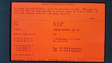
Historically, the BIOS in the IBM PC and XT had no built-in user interface. The BIOS versions in earlier PCs (XT-class) were not software configurable; instead, users set the options via DIP switches on the motherboard. Later computers, including all IBM-compatibles with 80286 CPUs, had a battery-backed nonvolatile BIOS memory (CMOS RAM chip) that held BIOS settings.[38] These settings, such as video-adapter type, memory size, and hard-disk parameters, could only be configured by running a configuration program from a disk, not built into the ROM. A special «reference diskette» was inserted in an IBM AT to configure settings such as memory size.
Early BIOS versions did not have passwords or boot-device selection options. The BIOS was hard-coded to boot from the first floppy drive, or, if that failed, the first hard disk. Access control in early AT-class machines was by a physical keylock switch (which was not hard to defeat if the computer case could be opened). Anyone who could switch on the computer could boot it.[citation needed]
Later, 386-class computers started integrating the BIOS setup utility in the ROM itself, alongside the BIOS code; these computers usually boot into the BIOS setup utility if a certain key or key combination is pressed, otherwise the BIOS POST and boot process are executed.
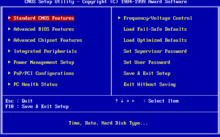
Award BIOS setup utility on a standard PC
A modern BIOS setup utility has a text user interface (TUI) or graphical user interface (GUI) accessed by pressing a certain key on the keyboard when the PC starts. Usually, the key is advertised for short time during the early startup, for example «Press DEL to enter Setup». The actual key depends on specific hardware. Features present in the BIOS setup utility typically include:
- Configuring, enabling and disabling the hardware components
- Setting the system time
- Setting the boot order
- Setting various passwords, such as a password for securing access to the BIOS user interface and preventing malicious users from booting the system from unauthorized portable storage devices, or a password for booting the system
Hardware monitoring[edit]
A modern BIOS setup screen often features a PC Health Status or a Hardware Monitoring tab, which directly interfaces with a Hardware Monitor chip of the mainboard.[39] This makes it possible to monitor CPU and chassis temperature, the voltage provided by the power supply unit, as well as monitor and control the speed of the fans connected to the motherboard.
Once the system is booted, hardware monitoring and computer fan control is normally done directly by the Hardware Monitor chip itself, which can be a separate chip, interfaced through I2C or SMBus, or come as a part of a Super I/O solution, interfaced through Industry Standard Architecture (ISA) or Low Pin Count (LPC).[40] Some operating systems, like NetBSD with envsys and OpenBSD with sysctl hw.sensors, feature integrated interfacing with hardware monitors.
However, in some circumstances, the BIOS also provides the underlying information about hardware monitoring through ACPI, in which case, the operating system may be using ACPI to perform hardware monitoring.[41][42]
Reprogramming[edit]

BIOS replacement kit for a Dell 310 from the late 1980s. Included are two chips, a plastic holder for the chips, and a chip puller.
In modern PCs the BIOS is stored in rewritable EEPROM or NOR flash memory, allowing the contents to be replaced and modified. This rewriting of the contents is sometimes termed flashing. It can be done by a special program, usually provided by the system’s manufacturer, or at POST, with a BIOS image in a hard drive or USB flash drive. A file containing such contents is sometimes termed «a BIOS image». A BIOS might be reflashed in order to upgrade to a newer version to fix bugs or provide improved performance or to support newer hardware.
Hardware[edit]

The original IBM PC BIOS (and cassette BASIC) was stored on mask-programmed read-only memory (ROM) chips in sockets on the motherboard. ROMs could be replaced, but not altered, by users. To allow for updates, many compatible computers used re-programmable BIOS memory devices such as EPROM, EEPROM and later flash memory (usually NOR flash) devices. According to Robert Braver, the president of the BIOS manufacturer Micro Firmware, Flash BIOS chips became common around 1995 because the electrically erasable PROM (EEPROM) chips are cheaper and easier to program than standard ultraviolet erasable PROM (EPROM) chips. Flash chips are programmed (and re-programmed) in-circuit, while EPROM chips need to be removed from the motherboard for re-programming.[43] BIOS versions are upgraded to take advantage of newer versions of hardware and to correct bugs in previous revisions of BIOSes.[44]
Beginning with the IBM AT, PCs supported a hardware clock settable through BIOS. It had a century bit which allowed for manually changing the century when the year 2000 happened. Most BIOS revisions created in 1995 and nearly all BIOS revisions in 1997 supported the year 2000 by setting the century bit automatically when the clock rolled past midnight, 31 December 1999.[45]
The first flash chips were attached to the ISA bus. Starting in 1998, the BIOS flash moved to the LPC bus, following a new standard implementation known as «firmware hub» (FWH). In 2005, the BIOS flash memory moved to the SPI bus.[46]
The size of the BIOS, and the capacity of the ROM, EEPROM, or other media it may be stored on, has increased over time as new features have been added to the code; BIOS versions now exist with sizes up to 32 megabytes. For contrast, the original IBM PC BIOS was contained in an 8 KB mask ROM. Some modern motherboards are including even bigger NAND flash memory ICs on board which are capable of storing whole compact operating systems, such as some Linux distributions. For example, some ASUS notebooks included Splashtop OS embedded into their NAND flash memory ICs.[47] However, the idea of including an operating system along with BIOS in the ROM of a PC is not new; in the 1980s, Microsoft offered a ROM option for MS-DOS, and it was included in the ROMs of some PC clones such as the Tandy 1000 HX.
Another type of firmware chip was found on the IBM PC AT and early compatibles. In the AT, the keyboard interface was controlled by a microcontroller with its own programmable memory. On the IBM AT, that was a 40-pin socketed device, while some manufacturers used an EPROM version of this chip which resembled an EPROM. This controller was also assigned the A20 gate function to manage memory above the one-megabyte range; occasionally an upgrade of this «keyboard BIOS» was necessary to take advantage of software that could use upper memory.[citation needed]
The BIOS may contain components such as the Memory Reference Code (MRC), which is responsible for the memory initialization (e.g. SPD and memory timings initialization).[48]: 8 [49]
Modern BIOS[50] includes
Intel Management Engine[51] or AMD Platform Security Processor firmware.
Vendors and products[edit]
| Company | AwardBIOS | AMIBIOS | Insyde | SeaBIOS |
|---|---|---|---|---|
| License | Proprietary | Proprietary | Proprietary | LGPL v3 |
| Maintained / developed | Terminated | Terminated | Terminated | Yes |
| 32-bit PCI BIOS calls | Yes | Yes | Yes | Yes |
| AHCI | Yes | Yes | Yes | Yes |
| APM | Yes | Yes | Yes (1.2) | Yes (1.2) |
| BBS | Yes | Yes | Yes | Yes |
| Boot menu | Yes | Yes | Yes | Yes |
| Compression | Yes (LHA[52]) | Yes (LHA) | Yes (RLE) | Yes (LZMA) |
| CMOS | Yes | Yes | Yes | Yes |
| EDD | Yes | Yes | Yes | Yes |
| ESCD | Yes | Yes | ? | No |
| Flash from ROM | ? | Yes | ? | No |
| Language | Assembly | Assembly | Assembly | C |
| LBA | Yes (48) | Yes (48) | Yes | Yes (48) |
| MultiProcessor Specification | Yes | Yes | Yes | Yes |
| Option ROM | Yes | Yes | Yes | Yes |
| Password | Yes | Yes | Yes | No |
| PMM | ? | Yes | ? | Yes |
| Setup screen | Yes | Yes | Yes | No |
| SMBIOS | Yes | Yes | Yes | Yes |
| Splash screen | Yes (EPA)[53] | Yes (PCX) | Yes | Yes (BMP, JPG) |
| TPM | Unknown | Unknown | Unknown | Some |
| USB booting | Yes | Yes | Yes | Yes |
| USB hub | ? | ? | ? | Yes |
| USB keyboard | Yes | Yes | Yes | Yes |
| USB mouse | Yes | Yes | Yes | Yes |
IBM published the entire listings of the BIOS for its original PC, PC XT, PC AT, and other contemporary PC models, in an appendix of the IBM PC Technical Reference Manual for each machine type. The effect of the publication of the BIOS listings is that anyone can see exactly what a definitive BIOS does and how it does it.
In May 1984 Phoenix Software Associates released its first ROM-BIOS, which enabled OEMs to build essentially fully compatible clones without having to reverse-engineer the IBM PC BIOS themselves, as Compaq had done for the Portable, helping fuel the growth in the PC-compatibles industry and sales of non-IBM versions of DOS.[54] And the first American Megatrends (AMI) BIOS was released on 1986.
New standards grafted onto the BIOS are usually without complete public documentation or any BIOS listings. As a result, it is not as easy to learn the intimate details about the many non-IBM additions to BIOS as about the core BIOS services.
Most PC motherboard suppliers licensed a BIOS «core» and toolkit from a commercial third party, known as an «independent BIOS vendor» or IBV. The motherboard manufacturer then customized this BIOS to suit its own hardware. For this reason, updated BIOSes are normally obtained directly from the motherboard manufacturer. Major IBV included American Megatrends (AMI), Insyde Software, Phoenix Technologies, and Byosoft. Microid Research and Award Software were acquired by Phoenix Technologies in 1998; Phoenix later phased out the Award brand name. General Software, which was also acquired by Phoenix in 2007, sold BIOS for embedded systems based on Intel processors.
The open-source community increased their effort to develop a replacement for proprietary BIOSes and their future incarnations with an open-sourced counterpart through the libreboot, coreboot and OpenBIOS/Open Firmware projects. AMD provided product specifications for some chipsets, and Google is sponsoring the project. Motherboard manufacturer Tyan offers coreboot next to the standard BIOS with their Opteron line of motherboards.
Security[edit]

An American Megatrends BIOS showing an «Intel CPU uCode Loading Error» after a failed attempt to upload microcode patches into the CPU

EEPROM and Flash memory chips are advantageous because they can be easily updated by the user; it is customary for hardware manufacturers to issue BIOS updates to upgrade their products, improve compatibility and remove bugs. However, this advantage had the risk that an improperly executed or aborted BIOS update could render the computer or device unusable. To avoid these situations, more recent BIOSes use a «boot block»; a portion of the BIOS which runs first and must be updated separately. This code verifies if the rest of the BIOS is intact (using hash checksums or other methods) before transferring control to it. If the boot block detects any corruption in the main BIOS, it will typically warn the user that a recovery process must be initiated by booting from removable media (floppy, CD or USB flash drive) so the user can try flashing the BIOS again. Some motherboards have a backup BIOS (sometimes referred to as DualBIOS boards) to recover from BIOS corruptions.
There are at least five known BIOS attack viruses, two of which were for demonstration purposes. The first one found in the wild was Mebromi, targeting Chinese users.
The first BIOS virus was BIOS Meningitis, which instead of erasing BIOS chips it infected them. BIOS Meningitis has relatively harmless, compared to a virus like CIH.
The second BIOS virus was CIH, also known as the «Chernobyl Virus», which was able to erase flash ROM BIOS content on compatible chipsets. CIH appeared in mid-1998 and became active in April 1999. Often, infected computers could no longer boot, and people had to remove the flash ROM IC from the motherboard and reprogram it. CIH targeted the then-widespread Intel i430TX motherboard chipset and took advantage of the fact that the Windows 9x operating systems, also widespread at the time, allowed direct hardware access to all programs.
Modern systems are not vulnerable to CIH because of a variety of chipsets being used which are incompatible with the Intel i430TX chipset, and also other flash ROM IC types. There is also extra protection from accidental BIOS rewrites in the form of boot blocks which are protected from accidental overwrite or dual and quad BIOS equipped systems which may, in the event of a crash, use a backup BIOS. Also, all modern operating systems such as FreeBSD, Linux, macOS, Windows NT-based Windows OS like Windows 2000, Windows XP and newer, do not allow user-mode programs to have direct hardware access using a hardware abstraction layer.[55]
As a result, as of 2008, CIH has become essentially harmless, at worst causing annoyance by infecting executable files and triggering antivirus software. Other BIOS viruses remain possible, however;[56] since most Windows home users without Windows Vista/7’s UAC run all applications with administrative privileges, a modern CIH-like virus could in principle still gain access to hardware without first using an exploit.[citation needed] The operating system OpenBSD prevents all users from having this access and the grsecurity patch for the Linux kernel also prevents this direct hardware access by default, the difference being an attacker requiring a much more difficult kernel level exploit or reboot of the machine.[citation needed]
The third BIOS virus was a technique presented by John Heasman, principal security consultant for UK-based Next-Generation Security Software. In 2006, at the Black Hat Security Conference, he showed how to elevate privileges and read physical memory, using malicious procedures that replaced normal ACPI functions stored in flash memory.[57]
The fourth BIOS virus was a technique called «Persistent BIOS infection.» It appeared in 2009 at the CanSecWest Security Conference in Vancouver, and at the SyScan Security Conference in Singapore. Researchers Anibal Sacco[58] and Alfredo Ortega, from Core Security Technologies, demonstrated how to insert malicious code into the decompression routines in the BIOS, allowing for nearly full control of the PC at start-up, even before the operating system is booted. The proof-of-concept does not exploit a flaw in the BIOS implementation, but only involves the normal BIOS flashing procedures. Thus, it requires physical access to the machine, or for the user to be root. Despite these requirements, Ortega underlined the profound implications of his and Sacco’s discovery: «We can patch a driver to drop a fully working rootkit. We even have a little code that can remove or disable antivirus.»[59]
Mebromi is a trojan which targets computers with AwardBIOS, Microsoft Windows, and antivirus software from two Chinese companies: Rising Antivirus and Jiangmin KV Antivirus.[60][61][62] Mebromi installs a rootkit which infects the Master boot record.
In a December 2013 interview with 60 Minutes, Deborah Plunkett, Information Assurance Director for the US National Security Agency claimed the NSA had uncovered and thwarted a possible BIOS attack by a foreign nation state, targeting the US financial system.[63] The program cited anonymous sources alleging it was a Chinese plot.[63] However follow-up articles in The Guardian,[64] The Atlantic,[65] Wired[66] and The Register[67] refuted the NSA’s claims.
Newer Intel platforms have Intel Boot Guard (IBG) technology enabled, this technology will check the BIOS digital signature at startup, and the IBG public key is fused into the PCH. End users can’t disable this function.
Alternatives and successors[edit]
For comparable software on other computer systems, see booting.
Unified Extensible Firmware Interface (UEFI) supplements the BIOS in many new machines. Initially written for the Intel Itanium architecture, UEFI is now available for x86 and ARM architecture platforms; the specification development is driven by the Unified EFI Forum, an industry Special Interest Group. EFI booting has been supported in only Microsoft Windows versions supporting GPT,[68] the Linux kernel 2.6.1 and later, and macOS on Intel-based Macs.[69] As of 2014, new PC hardware predominantly ships with UEFI firmware. The architecture of the rootkit safeguard can also prevent the system from running the user’s own software changes, which makes UEFI controversial as a legacy BIOS replacement in the open hardware community. Also, Windows 11 requires UEFI to boot.[70]
Other alternatives to the functionality of the «Legacy BIOS» in the x86 world include coreboot and libreboot.
Some servers and workstations use a platform-independent Open Firmware (IEEE-1275) based on the Forth programming language; it is included with Sun’s SPARC computers, IBM’s RS/6000 line, and other PowerPC systems such as the CHRP motherboards, along with the x86-based OLPC XO-1.
As of at least 2015, Apple has removed legacy BIOS support from MacBook Pro computers. As such the BIOS utility no longer supports the legacy option, and prints «Legacy mode not supported on this system». In 2017, Intel announced that it would remove legacy BIOS support by 2020. Since 2019, new Intel platform OEM PCs no longer support the legacy option.
See also[edit]
- Double boot
- Extended System Configuration Data (ESCD)
- Input/Output Control System
- Advanced Configuration and Power Interface (ACPI)
- Ralf Brown’s Interrupt List (RBIL) – interrupts, calls, interfaces, data structures, memory and port addresses, and processor opcodes for the x86 architecture
- System Management BIOS (SMBIOS)
- Unified Extensible Firmware Interface (UEFI)
Notes[edit]
- ^ The signature at offset
+0x1FEin boot sectors is0x55 0xAA, that is0x55at offset+0x1FEand0xAAat offset+0x1FF. Since little-endian representation must be assumed in the context of IBM PC compatible machines, this can be written as 16-bit word0xAA55in programs for x86 processors (note the swapped order), whereas it would have to be written as0x55AAin programs for other CPU architectures using a big-endian representation. Since this has been mixed up numerous times in books and even in original Microsoft reference documents, this article uses the offset-based byte-wise on-disk representation to avoid any possible misinterpretation.
References[edit]
- ^ «Ref — System BIOS». PCGuide. Archived from the original on 2014-12-21. Retrieved 2014-12-06.
- ^ «Unified Extensible Firmware Interface». Intel. Intel.
- ^ «UEFI». OSDev.org.
- ^ a b c Kildall, Gary Arlen (June 1975), CP/M 1.1 or 1.2 BIOS and BDOS for Lawrence Livermore Laboratories
- ^ a b c Kildall, Gary Arlen (January 1980). «The History of CP/M — The Evolution of an Industry: One Person’s Viewpoint» (Vol. 5, No. 1, Number 41 ed.). Dr. Dobb’s Journal of Computer Calisthenics & Orthodontia. pp. 6–7. Archived from the original on 2016-11-24. Retrieved 2013-06-03.
- ^ a b «Booting · Linux Inside». 0xax.gitbooks.io. Retrieved 2020-11-10.
- ^ a b Bradley, Tony. «R.I.P. BIOS: A UEFI Primer». PCWorld. Archived from the original on 2014-01-27. Retrieved 2014-01-27.
- ^ Swaine, Michael (1997-04-01). «Gary Kildall and Collegial Entrepreneurship». Dr. Dobb’s Journal. Archived from the original on 2007-01-24. Retrieved 2006-11-20.
- ^ a b «IEEE Milestone in Electrical Engineering and Computing — CP/M — Microcomputer Operating System, 1974» (PDF). Computer History Museum. 2014-04-25. Archived (PDF) from the original on 2019-04-03. Retrieved 2019-04-03.
- ^ Shustek, Len (2016-08-02). «In His Own Words: Gary Kildall». Remarkable People. Computer History Museum. Archived from the original on 2016-12-17.
- ^ Killian, A. Joseph «Joe» (2001). «Gary Kildall’s CP/M: Some early CP/M history — 1976-1977». Thomas «Todd» Fischer, IMSAI. Archived from the original on 2012-12-29. Retrieved 2013-06-03.
- ^ Fraley, Bob; Spicer, Dag (2007-01-26). «Oral History of Joseph Killian, Interviewed by: Bob Fraley, Edited by: Dag Spicer, Recorded: January 26, 2007, Mountain View, California, CHM Reference number: X3879.2007» (PDF). Computer History Museum. Archived from the original (PDF) on 2014-07-14. Retrieved 2013-06-03.
- ^ Glass, Brett (1989). «The IBM PC BIOS». Byte: 303–310. Retrieved 2021-12-31.
- ^ «HP BIOS Configuration Utility». Hewlett-Packard. 2013. Archived from the original on 2015-01-12. Retrieved 2015-01-12.
- ^ See Intel 64 and IA-32 Architectures Software Developer’s Manual Archived 2012-01-26 at the Wayback Machine, volume 3, section 9.1.2
- ^ page 5-27 IBM Personal Computer Hardware Reference Library Technical Reference, 1984, publication number 6361459
- ^ «IBM 5162 PC XT286 TechRef 68X2537 Technical Reference manual» (PDF). August 1986. p. 35 (System BIOS A-5). Archived (PDF) from the original on 2014-12-11. Retrieved 2014-12-11.
- ^ How StuffWorks: What BIOS Does Archived 2008-02-07 at the Wayback Machine.
- ^ Akeljic, Bekir (2017-01-01). «BIOS BASIC INPUT/ OUTPUT SYSTEM BIOS FUNCTIONS AND MODIFICATIONS». BIOS: 12. Archived from the original on 2022-08-08. Retrieved 2022-08-08 – via INTERNATIONAL UNIVERSITY TRAVNIKFACULITY OF INFORMATION TEHNOLOGY TRAVNIKSOFTWARE PROGRAMMING.
- ^ «BIOS — CodeDocs». codedocs.org. Retrieved 2022-08-08.
- ^ «Memory Layout and Memory Map». flint.cs.yale.edu. Retrieved 2022-08-08.
- ^ «BIOS Data ACPI Table (BDAT)» (PDF). Interface Specification. 4 (5): 67. 2020. Archived (PDF) from the original on 2021-07-03. Retrieved 2022-08-08.
- ^ Stiller, Andreas; Paul, Matthias R. (1996-05-12). «Prozessorgeflüster». c’t – magazin für computertechnik. Trends & News / aktuell — Prozessoren (in German). Vol. 1996, no. 6. Verlag Heinz Heise GmbH & Co KG. p. 20. ISSN 0724-8679. Archived from the original on 2017-08-28. Retrieved 2017-08-28.
- ^ Mueller, Scott (2001-06-08). Processor Update Feature | Microprocessor Types and Specifications. InformIT. Archived from the original on 2014-04-16. Retrieved 2014-04-15.
- ^ «Linux* Processor Microcode Data File». Download Center. Downloadcenter.intel.com. 2009-09-23. Archived from the original on 2014-04-16. Retrieved 2014-04-15.
- ^ Scott Mueller, Upgrading and repairing PCs 15th edition, Que Publishing, 2003 ISBN 0-7897-2974-1, pages 109-110
- ^ «KB4100347: Intel microcode updates». support.microsoft.com. Retrieved 2020-09-20.
- ^ «Microcode — Debian Wiki». wiki.debian.org. Retrieved 2020-09-19.
- ^ a b «How SLP and SLIC Works». guytechie.com. 2010-02-25. Archived from the original on 2015-02-03. Retrieved 2015-02-03.
- ^ «Create and add an OEM ACPI SLIC table module to a congatec BIOS» (PDF). congatec.com. 2011-06-16. Archived (PDF) from the original on 2014-08-02. Retrieved 2015-02-03.
- ^ Whitson Gordon (2014-01-13). «A Beginner’s Introduction to Overclocking Your Intel Processor». Lifehacker. Gawker Media. Archived from the original on 2014-12-07. Retrieved 2014-12-06.
- ^ Smart Computing Article — What Is The BIOS? Archived 2012-03-10 at the Wayback Machine — Computing Basics July 1994 • Vol.5 Issue 7
- ^ «What is ACPI (Advanced Configuration and Power Interface)? — Definition from WhatIs.com». SearchWindowsServer. Retrieved 2020-09-18.
- ^ «Changing hardware abstraction layer in Windows 2000 / XP – Smallvoid.com». Retrieved 2020-09-18.
- ^ «What is ACPI?». www.spo-comm.de. Retrieved 2020-09-18.
- ^ lorihollasch. «Support for headless systems — Windows drivers». docs.microsoft.com. Retrieved 2020-12-05.
- ^ «Memory Map (x86) — OSDev Wiki». wiki.osdev.org. Retrieved 2020-12-11.
- ^ Torres, Gabriel (2004-11-24). «Introduction and Lithium Battery». Replacing the Motherboard Battery. hardwaresecrets.com. Archived from the original on 2013-12-24. Retrieved 2013-06-20.
- ^ Constantine A. Murenin (2010-05-21). «11.1. Interfacing from the BIOS». OpenBSD Hardware Sensors – Environmental Monitoring and Fan Control (MMath thesis). University of Waterloo: UWSpace. hdl:10012/5234. Document ID: ab71498b6b1a60ff817b29d56997a418.
- ^ Constantine A. Murenin (2007-04-17). «2. Hardware review». Generalised Interfacing with Microprocessor System Hardware Monitors. Proceedings of 2007 IEEE International Conference on Networking, Sensing and Control, 15–17 April 2007. London, United Kingdom: IEEE. pp. 901–906. doi:10.1109/ICNSC.2007.372901. ISBN 978-1-4244-1076-7. IEEE ICNSC 2007, pp. 901—906.
- ^ «aibs – ASUSTeK AI Booster ACPI ATK0110 voltage, temperature and fan sensor». OpenBSD, DragonFly BSD, NetBSD and FreeBSD. 2010.
- ^ «acpi_thermal(4)». www.freebsd.org. Retrieved 2021-02-24.
- ^ «Decoding RAM & ROM Archived 2012-04-06 at the Wayback Machine.» Smart Computing. June 1997. Volume 8, Issue 6.
- ^ «Upgrading Your Flash BIOS For Plug And Play Archived 2012-04-06 at the Wayback Machine.» Smart Computing. March 1996. Volume 7, Issue 3.
- ^ «Time To Check BIOS Archived 2011-07-16 at the Wayback Machine.» Smart Computing. April 1999. Volume 7, Issue 4.
- ^ «Archived copy». Archived from the original on 2021-08-18. Retrieved 2021-04-01.
{{cite web}}: CS1 maint: archived copy as title (link) - ^ «SplashTop’s Instant-On Linux Desktop | Geek.com». Archived from the original on 2008-09-07.
- ^ Posted by Alex Watson, possibly repost from original content on custompc.com [unclear]. «The life and times of the modern motherboard». 2007-11-27. Archived from the original on 2012-07-24. Retrieved 2013-02-02.
- ^ David Hilber Jr. (August 2009). «Considerations for Designing an Embedded Intel Architecture System with System Memory Down» (PDF). Intel. Archived (PDF) from the original on 2012-10-18. Retrieved 2013-02-02.
- ^ «Types of BIOS». rompacks.com. Retrieved 2021-09-20.
- ^ «ME — flashrom». www.flashrom.org. Retrieved 2020-09-19.
- ^ Stiller, Andreas (2001). «Prozessor-Patches». c’t (in German). Heise (5): 240. Archived from the original on 2015-11-22. Retrieved 2015-11-21.
- ^ «Award BIOS logo». 2015-06-15. Archived from the original on 2015-12-21. Retrieved 2015-12-06.
- ^ Phoenix Eagerly Waiting to Clone Next-Generation IBM BIOS. Archived 2014-01-22 at the Wayback Machine, InfoWorld, 9 March 1987.
- ^ «Definition of hardware abstraction layer». PCMAG. Retrieved 2022-07-11.
- ^ New BIOS Virus Withstands HDD Wipes, 27 March 2009. Marcus Yam. Tom’s Hardware US
- ^ «Black Hat 2006 Multimedia — Presentation, Audio and Video Archives». www.blackhat.com. Retrieved 2019-04-21.
- ^ Sacco, Anibal; Alfredo Ortéga (2009-03-23). «Persistent BIOS Infection». Exploiting Stuff. Archived from the original on 2009-08-04. Retrieved 2010-02-06.
- ^ Fisher, Dennis. «Researchers unveil persistent BIOS attack methods». Threat Post. Archived from the original on 2010-01-30. Retrieved 2010-02-06.
- ^ Giuliani, Marco (2011-09-13). «Mebromi: the first BIOS rootkit in the wild». blog. Archived from the original on 2011-09-23. Retrieved 2011-09-19.
- ^ «360发布»BMW病毒»技术分析报告». blog. Archived from the original on 2011-09-25. Retrieved 2011-09-19.
- ^ Yuan, Liang. «Trojan.Mebromi». Threat Response. Archived from the original on 2011-09-23. Retrieved 2011-09-19.
- ^ a b «How did 60 Minutes get cameras into a spy agency?». CBS News. Archived from the original on 2014-04-22. Retrieved 2014-04-15.
- ^ Spencer Ackerman in Washington (2013-12-16). «NSA goes on 60 Minutes: the definitive facts behind CBS’s flawed report». theguardian.com. Archived from the original on 2014-01-25. Retrieved 2014-01-27.
- ^ Friedersdorf, Conor (2013-12-16). «A Question for 60 Minutes: Why Would China Want to Destroy the Global Economy?». The Atlantic. Retrieved 2019-03-26.
- ^ Poulsen, Kevin (2013-12-16). «60 Minutes Puff Piece Claims NSA Saved U.S. From Cyberterrorism». Wired. ISSN 1059-1028. Retrieved 2019-03-26 – via www.wired.com.
- ^ Sharwood, Simon (2013-12-16). «NSA alleges ‘BIOS plot to destroy PCs’«. The Register. Retrieved 2019-03-26.
- ^ «Windows and GPT FAQ». microsoft.com. Microsoft. Archived from the original on 2011-02-19. Retrieved 2014-12-06.
- ^ «Extensible Firmware Interface (EFI) and Unified EFI (UEFI)». Intel. Archived from the original on 2010-01-05. Retrieved 2014-12-06.
- ^ «Windows 11 Specs and System Requirements | Microsoft». Microsoft. Retrieved 2021-10-14.
Further reading[edit]
- IBM Personal Computer Technical Reference (Revised ed.). IBM Corporation. March 1983.
- IBM Personal Computer AT Technical Reference. IBM Personal Computer Hardware Reference Library. Vol. 0, 1, 2 (Revised ed.). IBM Corporation. March 1986 [1984-03]. 1502494, 6139362, 6183310, 6183312, 6183355, 6280070, 6280099.
- Phoenix Technologies, Ltd. (1989) [1987]. System BIOS for IBM PC/XT/AT Computers and Compatibles — The Complete Guide to ROM-Based System Software. Phoenix Technical Reference Series (1st ed.). Addison Wesley Publishing Company, Inc. ISBN 0-201-51806-6.
- Phoenix Technologies, Ltd. (1989) [1987]. CBIOS for IBM PS/2 Computers and Compatibles — The Complete Guide to ROM-Based System Software for DOS. Phoenix Technical Reference Series (1st ed.). Addison Wesley Publishing Company, Inc. ISBN 0-201-51804-X.
- Phoenix Technologies, Ltd. (1989) [1987]. ABIOS for IBM PS/2 Computers and Compatibles — The Complete Guide to ROM-Based System Software for OS/2. Phoenix Technical Reference Series (1st ed.). Addison Wesley Publishing Company, Inc. ISBN 0-201-51805-8.
- Phoenix Technologies, Ltd. (June 1991). System BIOS for IBM PCs, Compatibles, and EISA Computers — The Complete Guide to ROM-Based System Software. Phoenix Technical Reference Series (2nd ed.). Amsterdam: Addison Wesley Publishing Company, Inc. ISBN 0-201-57760-7.
- BIOS Disassembly Ninjutsu Uncovered, 1st edition, a freely available book in PDF format
- More Power To Firmware, free bonus chapter to the Mac OS X Internals: A Systems Approach book
External links[edit]
![]()
Wikimedia Commons has media related to the BIOS.
![]()
Look up BIOS in Wiktionary, the free dictionary.
- «BIOS Boot Specification 1.01» (PDF). Phoenix.com. 1996-01-11. Archived from the original (PDF) on 2011-07-15.
- «How BIOS Works». How Stuff Works. 2000-09-06.
- «Implementing a Plug and Play BIOS Using Intel’s Boot Block Flash Memory» (PDF). Intel. February 1995. Archived from the original (PDF) on 2007-11-28. Retrieved 2007-11-28.
- «List of BIOS options». techarp.com. Archived from the original on 2014-01-27.
- «Persistent BIOS Infection». Phrack. No. 66. 2009-06-01. Archived from the original on 2011-04-30. Retrieved 2011-04-30.
- «Preventing BIOS Failures Using Intel Boot Block Flash Memory» (PDF). Intel. December 1998. Archived from the original (PDF) on 2007-03-29. Retrieved 2007-03-29.
This article is about the BIOS as found in personal computers. For other uses, see Bios (disambiguation).
A pair of AMD BIOS chips for a Dell 310 computer from the 1980s. The bottom one shows the distinct window of an EPROM chip.
In computing, BIOS (, BY-oss, -ohss; Basic Input/Output System, also known as the System BIOS, ROM BIOS, BIOS ROM or PC BIOS) is firmware used to provide runtime services for operating systems and programs and to perform hardware initialization during the booting process (power-on startup).[1] The BIOS firmware comes pre-installed on an IBM PC or IBM PC compatible’s system board and exists in some UEFI-based systems to maintain compatibility with operating systems that do not support UEFI native operation.[2][3] The name originates from the Basic Input/Output System used in the CP/M operating system in 1975.[4][5] The BIOS originally proprietary to the IBM PC has been reverse engineered by some companies (such as Phoenix Technologies) looking to create compatible systems. The interface of that original system serves as a de facto standard.
The BIOS in modern PCs initializes and tests the system hardware components (Power-on self-test), and loads a boot loader from a mass storage device which then initializes a kernel. In the era of DOS, the BIOS provided BIOS interrupt calls for the keyboard, display, storage, and other input/output (I/O) devices that standardized an interface to application programs and the operating system. More recent operating systems do not use the BIOS interrupt calls after startup.[6]
Most BIOS implementations are specifically designed to work with a particular computer or motherboard model, by interfacing with various devices especially system chipset. Originally, BIOS firmware was stored in a ROM chip on the PC motherboard. In later computer systems, the BIOS contents are stored on flash memory so it can be rewritten without removing the chip from the motherboard. This allows easy, end-user updates to the BIOS firmware so new features can be added or bugs can be fixed, but it also creates a possibility for the computer to become infected with BIOS rootkits. Furthermore, a BIOS upgrade that fails could brick the motherboard. The last version of Microsoft Windows running on PCs which uses BIOS firmware is Windows 10.
Unified Extensible Firmware Interface (UEFI) is a successor to the legacy PC BIOS, aiming to address its technical limitations.[7]
History[edit]
/* C P / M   B A S I C   I / O    S Y S T E M    (B I O S)
                    COPYRIGHT (C) GARY A. KILDALL
                             JUNE, 1975 */
[…]
/*  B A S I C   D I S K    O P E R A T I N G   S Y S T E M  (B D O S)
                    COPYRIGHT (C) GARY A. KILDALL
                            JUNE, 1975 */
The term BIOS (Basic Input/Output System) was created by Gary Kildall[8][9] and first appeared in the CP/M operating system in 1975,[4][5][9][10][11][12] describing the machine-specific part of CP/M loaded during boot time that interfaces directly with the hardware.[5] (A CP/M machine usually has only a simple boot loader in its ROM.)
Versions of MS-DOS, PC DOS or DR-DOS contain a file called variously «IO.SYS», «IBMBIO.COM», «IBMBIO.SYS», or «DRBIOS.SYS»; this file is known as the «DOS BIOS» (also known as the «DOS I/O System») and contains the lower-level hardware-specific part of the operating system. Together with the underlying hardware-specific but operating system-independent «System BIOS», which resides in ROM, it represents the analogue to the «CP/M BIOS».
The BIOS originally proprietary to the IBM PC has been reverse engineered by some companies (such as Phoenix Technologies) looking to create compatible systems.
With the introduction of PS/2 machines, IBM divided the System BIOS into real- and protected-mode portions. The real-mode portion was meant to provide backward compatibility with existing operating systems such as DOS, and therefore was named «CBIOS» (for «Compatibility BIOS»), whereas the «ABIOS» (for «Advanced BIOS») provided new interfaces specifically suited for multitasking operating systems such as OS/2.[13]
User interface[edit]
The BIOS of the original IBM PC and XT had no interactive user interface. Error codes or messages were displayed on the screen, or coded series of sounds were generated to signal errors when the power-on self-test (POST) had not proceeded to the point of successfully initializing a video display adapter. Options on the IBM PC and XT were set by switches and jumpers on the main board and on expansion cards. Starting around the mid-1990s, it became typical for the BIOS ROM to include a «BIOS configuration utility» (BCU[14]) or «BIOS setup utility», accessed at system power-up by a particular key sequence. This program allowed the user to set system configuration options, of the type formerly set using DIP switches, through an interactive menu system controlled through the keyboard. In the interim period, IBM-compatible PCs—including the IBM AT—held configuration settings in battery-backed RAM and used a bootable configuration program on floppy disk, not in the ROM, to set the configuration options contained in this memory. The floppy disk was supplied with the computer, and if it was lost the system settings could not be changed. The same applied in general to computers with an EISA bus, for which the configuration program was called an EISA Configuration Utility (ECU).
A modern Wintel-compatible computer provides a setup routine essentially unchanged in nature from the ROM-resident BIOS setup utilities of the late 1990s; the user can configure hardware options using the keyboard and video display. The modern Wintel machine may store the BIOS configuration settings in flash ROM, perhaps the same flash ROM that holds the BIOS itself.
Operation[edit]
System startup[edit]
Early Intel processors started at physical address 000FFFF0h. Systems with later processors provide logic to start running the BIOS from the system ROM.
[15]
If the system has just been powered up or the reset button was pressed («cold boot»), the full power-on self-test (POST) is run. If Ctrl+Alt+Delete was pressed («warm boot»), a special flag value stored in nonvolatile BIOS memory («CMOS») tested by the BIOS allows bypass of the lengthy POST and memory detection.
The POST identifies, tests and initializes system devices such as the CPU, chipset, RAM, motherboard, video card, keyboard, mouse, hard disk drive, optical disc drive and other hardware, including integrated peripherals.
Early IBM PCs had a routine in the POST that would download a program into RAM through the keyboard port and run it.[16][17] This feature was intended for factory test or diagnostic purposes.
Boot process[edit]
After the option ROM scan is completed and all detected ROM modules with valid checksums have been called, or immediately after POST in a BIOS version that does not scan for option ROMs, the BIOS calls INT 19h to start boot processing. Post-boot, programs loaded can also call INT 19h to reboot the system, but they must be careful to disable interrupts and other asynchronous hardware processes that may interfere with the BIOS rebooting process, or else the system may hang or crash while it is rebooting.
When INT 19h is called, the BIOS attempts to locate boot loader software on a «boot device», such as a hard disk, a floppy disk, CD, or DVD. It loads and executes the first boot software it finds, giving it control of the PC.[18]
The BIOS uses the boot devices set in Nonvolatile BIOS memory (CMOS), or, in the earliest PCs, DIP switches. The BIOS checks each device in order to see if it is bootable by attempting to load the first sector (boot sector). If the sector cannot be read, the BIOS proceeds to the next device. If the sector is read successfully, some BIOSes will also check for the boot sector signature 0x55 0xAA in the last two bytes of the sector (which is 512 bytes long), before accepting a boot sector and considering the device bootable.[nb 1]
When a bootable device is found, the BIOS transfers control to the loaded sector. The BIOS does not interpret the contents of the boot sector other than to possibly check for the boot sector signature in the last two bytes. Interpretation of data structures like partition tables and BIOS Parameter Blocks is done by the boot program in the boot sector itself or by other programs loaded through the boot process.
A non-disk device such as a network adapter attempts booting by a procedure that is defined by its option ROM or the equivalent integrated into the motherboard BIOS ROM. As such, option ROMs may also influence or supplant the boot process defined by the motherboard BIOS ROM.
With the El Torito optical media boot standard, the optical drive actually emulates a 3.5″ high-density floppy disk to the BIOS for boot purposes. Reading the «first sector» of a CD-ROM or DVD-ROM is not a simply defined operation like it is on a floppy disk or a hard disk. Furthermore, the complexity of the medium makes it difficult to write a useful boot program in one sector. The bootable virtual floppy disk can contain software that provides access to the optical medium in its native format.
Boot priority[edit]
The user can select the boot priority implemented by the BIOS. For example, most computers have a hard disk that is bootable, but sometimes there is a removable-media drive that has higher boot priority, so the user can cause a removable disk to be booted.
In most modern BIOSes, the boot priority order can be configured by the user. In older BIOSes, limited boot priority options are selectable; in the earliest BIOSes, a fixed priority scheme was implemented, with floppy disk drives first, fixed disks (i.e. hard disks) second, and typically no other boot devices supported, subject to modification of these rules by installed option ROMs. The BIOS in an early PC also usually would only boot from the first floppy disk drive or the first hard disk drive, even if there were two drives installed.
Boot failure[edit]
On the original IBM PC and XT, if no bootable disk was found, ROM BASIC was started by calling INT 18h. Since few programs used BASIC in ROM, clone PC makers left it out; then a computer that failed to boot from a disk would display «No ROM BASIC» and halt (in response to INT 18h).
Later computers would display a message like «No bootable disk found»; some would prompt for a disk to be inserted and a key to be pressed to retry the boot process. A modern BIOS may display nothing or may automatically enter the BIOS configuration utility when the boot process fails.
Boot environment[edit]
The environment for the boot program is very simple: the CPU is in real mode and the general-purpose and segment registers are undefined, except SS, SP, CS, and DL. CS:IP always points to physical address 0x07C00. What values CS and IP actually have is not well defined. Some BIOSes use a CS:IP of 0x0000:0x7C00 while others may use 0x07C0:0x0000.[19] Because boot programs are always loaded at this fixed address, there is no need for a boot program to be relocatable. DL may contain the drive number, as used with INT 13h, of the boot device. SS:SP points to a valid stack that is presumably large enough to support hardware interrupts, but otherwise SS and SP are undefined. (A stack must be already set up in order for interrupts to be serviced, and interrupts must be enabled in order for the system timer-tick interrupt, which BIOS always uses at least to maintain the time-of-day count and which it initializes during POST, to be active and for the keyboard to work. The keyboard works even if the BIOS keyboard service is not called; keystrokes are received and placed in the 15-character type-ahead buffer maintained by BIOS.) The boot program must set up its own stack, because the size of the stack set up by BIOS is unknown and its location is likewise variable; although the boot program can investigate the default stack by examining SS:SP, it is easier and shorter to just unconditionally set up a new stack.[20]
At boot time, all BIOS services are available, and the memory below address 0x00400 contains the interrupt vector table. BIOS POST has initialized the system timers, interrupt controller(s), DMA controller(s), and other motherboard/chipset hardware as necessary to bring all BIOS services to ready status. DRAM refresh for all system DRAM in conventional memory and extended memory, but not necessarily expanded memory, has been set up and is running. The interrupt vectors corresponding to the BIOS interrupts have been set to point at the appropriate entry points in the BIOS, hardware interrupt vectors for devices initialized by the BIOS have been set to point to the BIOS-provided ISRs, and some other interrupts, including ones that BIOS generates for programs to hook, have been set to a default dummy ISR that immediately returns. The BIOS maintains a reserved block of system RAM at addresses 0x00400–0x004FF with various parameters initialized during the POST. All memory at and above address 0x00500 can be used by the boot program; it may even overwrite itself.[21][22]
Extensions (option ROMs)[edit]
Peripheral cards such as hard disk drive host bus adapters and video cards have their own firmware, and BIOS extension option ROM may be a part of the expansion card firmware, which provide additional functionality to BIOS. Code in option ROMs runs before the BIOS boots the operating system from mass storage. These ROMs typically test and initialize hardware, add new BIOS services, or replace existing BIOS services with their own services. For example, a SCSI controller usually has a BIOS extension ROM that adds support for hard drives connected through that controller. An extension ROM could in principle contain operating system, or it could implement an entirely different boot process such as network booting. Operation of an IBM-compatible computer system can be completely changed by removing or inserting an adapter card (or a ROM chip) that contains a BIOS extension ROM.
The motherboard BIOS typically contains code for initializing and bootstrapping integrated display and integrated storage. In addition, plug-in adapter cards such as SCSI, RAID, network interface cards, and video cards often include their own BIOS (e.g. Video BIOS), complementing or replacing the system BIOS code for the given component. Even devices built into the motherboard can behave in this way; their option ROMs can be a part of the motherboard BIOS.
An add-in card requires an option ROM if the card is not supported by the motherboard BIOS and the card needs to be initialized or made accessible through BIOS services before the operating system can be loaded (usually this means it is required in the boot process). An additional advantage of ROM on some early PC systems (notably including the IBM PCjr) was that ROM was faster than main system RAM. (On modern systems, the case is very much the reverse of this, and BIOS ROM code is usually copied («shadowed») into RAM so it will run faster.)
Boot procedure[edit]
If an expansion ROM wishes to change the way the system boots (such as from a network device or a SCSI adapter) in a cooperative way, it can use the BIOS Boot Specification (BBS) API to register its ability to do so. Once the expansion ROMs have registered using the BBS APIs, the user can select among the available boot options from within the BIOS’s user interface. This is why most BBS compliant PC BIOS implementations will not allow the user to enter the BIOS’s user interface until the expansion ROMs have finished executing and registering themselves with the BBS API.[citation needed]
Also, if an expansion ROM wishes to change the way the system boots unilaterally, it can simply hook INT 19h or other interrupts normally called from interrupt 19h, such as INT 13h, the BIOS disk service, to intercept the BIOS boot process. Then it can replace the BIOS boot process with one of its own, or it can merely modify the boot sequence by inserting its own boot actions into it, by preventing the BIOS from detecting certain devices as bootable, or both. Before the BIOS Boot Specification was promulgated, this was the only way for expansion ROMs to implement boot capability for devices not supported for booting by the native BIOS of the motherboard.[citation needed]
Initialization[edit]
After the motherboard BIOS completes its POST, most BIOS versions search for option ROM modules, also called BIOS extension ROMs, and execute them. The motherboard BIOS scans for extension ROMs in a portion of the «upper memory area» (the part of the x86 real-mode address space at and above address 0xA0000) and runs each ROM found, in order. To discover memory-mapped option ROMs, a BIOS implementation scans the real-mode address space from 0x0C0000 to 0x0F0000 on 2 KB (2,048 bytes) boundaries, looking for a two-byte ROM signature: 0x55 followed by 0xAA. In a valid expansion ROM, this signature is followed by a single byte indicating the number of 512-byte blocks the expansion ROM occupies in real memory, and the next byte is the option ROM’s entry point (also known as its «entry offset»). If the ROM has a valid checksum, the BIOS transfers control to the entry address, which in a normal BIOS extension ROM should be the beginning of the extension’s initialization routine.
At this point, the extension ROM code takes over, typically testing and initializing the hardware it controls and registering interrupt vectors for use by post-boot applications. It may use BIOS services (including those provided by previously initialized option ROMs) to provide a user configuration interface, to display diagnostic information, or to do anything else that it requires. It is possible that an option ROM will not return to BIOS, pre-empting the BIOS’s boot sequence altogether.
An option ROM should normally return to the BIOS after completing its initialization process. Once (and if) an option ROM returns, the BIOS continues searching for more option ROMs, calling each as it is found, until the entire option ROM area in the memory space has been scanned.
Physical placement[edit]
BIOS chips in a Dell 310 that were updated by replacing the chips
Option ROMs normally reside on adapter cards. However, the original PC, and perhaps also the PC XT, have a spare ROM socket on the motherboard (the «system board» in IBM’s terms) into which an option ROM can be inserted, and the four ROMs that contain the BASIC interpreter can also be removed and replaced with custom ROMs which can be option ROMs. The IBM PCjr is unique among PCs in having two ROM cartridge slots on the front. Cartridges in these slots map into the same region of the upper memory area used for option ROMs, and the cartridges can contain option ROM modules that the BIOS would recognize. The cartridges can also contain other types of ROM modules, such as BASIC programs, that are handled differently. One PCjr cartridge can contain several ROM modules of different types, possibly stored together in one ROM chip.
Operating system services[edit]
The BIOS ROM is customized to the particular manufacturer’s hardware, allowing low-level services (such as reading a keystroke or writing a sector of data to diskette) to be provided in a standardized way to programs, including operating systems. For example, an IBM PC might have either a monochrome or a color display adapter (using different display memory addresses and hardware), but a single, standard, BIOS system call may be invoked to display a character at a specified position on the screen in text mode or graphics mode.
The BIOS provides a small library of basic input/output functions to operate peripherals (such as the keyboard, rudimentary text and graphics display functions and so forth). When using MS-DOS, BIOS services could be accessed by an application program (or by MS-DOS) by executing an INT 13h interrupt instruction to access disk functions, or by executing one of a number of other documented BIOS interrupt calls to access video display, keyboard, cassette, and other device functions.
Operating systems and executive software that are designed to supersede this basic firmware functionality provide replacement software interfaces to application software. Applications can also provide these services to themselves. This began even in the 1980s under MS-DOS, when programmers observed that using the BIOS video services for graphics display were very slow. To increase the speed of screen output, many programs bypassed the BIOS and programmed the video display hardware directly. Other graphics programmers, particularly but not exclusively in the demoscene, observed that there were technical capabilities of the PC display adapters that were not supported by the IBM BIOS and could not be taken advantage of without circumventing it. Since the AT-compatible BIOS ran in Intel real mode, operating systems that ran in protected mode on 286 and later processors required hardware device drivers compatible with protected mode operation to replace BIOS services.
In modern PCs running modern operating systems (such as Windows and Linux) the BIOS interrupt calls is used only during booting and initial loading of operating systems. Before the operating system’s first graphical screen is displayed, input and output are typically handled through BIOS. A boot menu such as the textual menu of Windows, which allows users to choose an operating system to boot, to boot into the safe mode, or to use the last known good configuration, is displayed through BIOS and receives keyboard input through BIOS.[6]
Many modern PCs can still boot and run legacy operating systems such as MS-DOS or DR-DOS that rely heavily on BIOS for their console and disk I/O, providing that the system has a BIOS, or a CSM-capable UEFI firmware.
Processor microcode updates[edit]
Intel processors have reprogrammable microcode since the P6 microarchitecture.[23][24][25] AMD processors have reprogrammable microcode since the K7 microarchitecture. The BIOS contain patches to the processor microcode that fix errors in the initial processor microcode; microcode is loaded into processor’s SRAM so reprogramming is not persistent, thus loading of microcode updates is performed each time the system is powered up. Without reprogrammable microcode, an expensive processor swap would be required;[26] for example, the Pentium FDIV bug became an expensive fiasco for Intel as it required a product recall because the original Pentium processor’s defective microcode could not be reprogrammed. Operating systems can update main processor microcode also.[27][28]
Identification[edit]
Some BIOSes contain a software licensing description table (SLIC), a digital signature placed inside the BIOS by the original equipment manufacturer (OEM), for example Dell. The SLIC is inserted into the ACPI data table and contains no active code.[29][30]
Computer manufacturers that distribute OEM versions of Microsoft Windows and Microsoft application software can use the SLIC to authenticate licensing to the OEM Windows Installation disk and system recovery disc containing Windows software. Systems with a SLIC can be preactivated with an OEM product key, and they verify an XML formatted OEM certificate against the SLIC in the BIOS as a means of self-activating (see System Locked Preinstallation, SLP). If a user performs a fresh install of Windows, they will need to have possession of both the OEM key (either SLP or COA) and the digital certificate for their SLIC in order to bypass activation.[29] This can be achieved if the user performs a restore using a pre-customised image provided by the OEM. Power users can copy the necessary certificate files from the OEM image, decode the SLP product key, then perform SLP activation manually. Cracks for non-genuine Windows distributions usually edit the SLIC or emulate it in order to bypass Windows activation.[citation needed]
Overclocking[edit]
Some BIOS implementations allow overclocking, an action in which the CPU is adjusted to a higher clock rate than its manufacturer rating for guaranteed capability. Overclocking may, however, seriously compromise system reliability in insufficiently cooled computers and generally shorten component lifespan. Overclocking, when incorrectly performed, may also cause components to overheat so quickly that they mechanically destroy themselves.[31]
Modern use[edit]
Some older operating systems, for example MS-DOS, rely on the BIOS to carry out most input/output tasks within the PC.[32]
Calling real mode BIOS services directly is inefficient for protected mode (and long mode) operating systems. BIOS interrupt calls are not used by modern multitasking operating systems after they initially load.
In 1990s, BIOS provided some protected mode interfaces for Microsoft Windows and Unix-like operating systems, such as Advanced Power Management (APM), Plug and Play BIOS, Desktop Management Interface (DMI), VESA BIOS Extensions (VBE), e820 and MultiProcessor Specification (MPS). Starting from the 2000, most BIOSes provide ACPI, SMBIOS, VBE and e820 interfaces for modern operating systems.[33][34][35][36][37]
After operating systems load, the System Management Mode code is still running in SMRAM. Since 2010, BIOS technology is in a transitional process toward UEFI.[7]
Configuration[edit]
Setup utility[edit]
Historically, the BIOS in the IBM PC and XT had no built-in user interface. The BIOS versions in earlier PCs (XT-class) were not software configurable; instead, users set the options via DIP switches on the motherboard. Later computers, including all IBM-compatibles with 80286 CPUs, had a battery-backed nonvolatile BIOS memory (CMOS RAM chip) that held BIOS settings.[38] These settings, such as video-adapter type, memory size, and hard-disk parameters, could only be configured by running a configuration program from a disk, not built into the ROM. A special «reference diskette» was inserted in an IBM AT to configure settings such as memory size.
Early BIOS versions did not have passwords or boot-device selection options. The BIOS was hard-coded to boot from the first floppy drive, or, if that failed, the first hard disk. Access control in early AT-class machines was by a physical keylock switch (which was not hard to defeat if the computer case could be opened). Anyone who could switch on the computer could boot it.[citation needed]
Later, 386-class computers started integrating the BIOS setup utility in the ROM itself, alongside the BIOS code; these computers usually boot into the BIOS setup utility if a certain key or key combination is pressed, otherwise the BIOS POST and boot process are executed.
Award BIOS setup utility on a standard PC
A modern BIOS setup utility has a text user interface (TUI) or graphical user interface (GUI) accessed by pressing a certain key on the keyboard when the PC starts. Usually, the key is advertised for short time during the early startup, for example «Press DEL to enter Setup». The actual key depends on specific hardware. Features present in the BIOS setup utility typically include:
- Configuring, enabling and disabling the hardware components
- Setting the system time
- Setting the boot order
- Setting various passwords, such as a password for securing access to the BIOS user interface and preventing malicious users from booting the system from unauthorized portable storage devices, or a password for booting the system
Hardware monitoring[edit]
A modern BIOS setup screen often features a PC Health Status or a Hardware Monitoring tab, which directly interfaces with a Hardware Monitor chip of the mainboard.[39] This makes it possible to monitor CPU and chassis temperature, the voltage provided by the power supply unit, as well as monitor and control the speed of the fans connected to the motherboard.
Once the system is booted, hardware monitoring and computer fan control is normally done directly by the Hardware Monitor chip itself, which can be a separate chip, interfaced through I2C or SMBus, or come as a part of a Super I/O solution, interfaced through Industry Standard Architecture (ISA) or Low Pin Count (LPC).[40] Some operating systems, like NetBSD with envsys and OpenBSD with sysctl hw.sensors, feature integrated interfacing with hardware monitors.
However, in some circumstances, the BIOS also provides the underlying information about hardware monitoring through ACPI, in which case, the operating system may be using ACPI to perform hardware monitoring.[41][42]
Reprogramming[edit]
BIOS replacement kit for a Dell 310 from the late 1980s. Included are two chips, a plastic holder for the chips, and a chip puller.
In modern PCs the BIOS is stored in rewritable EEPROM or NOR flash memory, allowing the contents to be replaced and modified. This rewriting of the contents is sometimes termed flashing. It can be done by a special program, usually provided by the system’s manufacturer, or at POST, with a BIOS image in a hard drive or USB flash drive. A file containing such contents is sometimes termed «a BIOS image». A BIOS might be reflashed in order to upgrade to a newer version to fix bugs or provide improved performance or to support newer hardware.
Hardware[edit]
The original IBM PC BIOS (and cassette BASIC) was stored on mask-programmed read-only memory (ROM) chips in sockets on the motherboard. ROMs could be replaced, but not altered, by users. To allow for updates, many compatible computers used re-programmable BIOS memory devices such as EPROM, EEPROM and later flash memory (usually NOR flash) devices. According to Robert Braver, the president of the BIOS manufacturer Micro Firmware, Flash BIOS chips became common around 1995 because the electrically erasable PROM (EEPROM) chips are cheaper and easier to program than standard ultraviolet erasable PROM (EPROM) chips. Flash chips are programmed (and re-programmed) in-circuit, while EPROM chips need to be removed from the motherboard for re-programming.[43] BIOS versions are upgraded to take advantage of newer versions of hardware and to correct bugs in previous revisions of BIOSes.[44]
Beginning with the IBM AT, PCs supported a hardware clock settable through BIOS. It had a century bit which allowed for manually changing the century when the year 2000 happened. Most BIOS revisions created in 1995 and nearly all BIOS revisions in 1997 supported the year 2000 by setting the century bit automatically when the clock rolled past midnight, 31 December 1999.[45]
The first flash chips were attached to the ISA bus. Starting in 1998, the BIOS flash moved to the LPC bus, following a new standard implementation known as «firmware hub» (FWH). In 2005, the BIOS flash memory moved to the SPI bus.[46]
The size of the BIOS, and the capacity of the ROM, EEPROM, or other media it may be stored on, has increased over time as new features have been added to the code; BIOS versions now exist with sizes up to 32 megabytes. For contrast, the original IBM PC BIOS was contained in an 8 KB mask ROM. Some modern motherboards are including even bigger NAND flash memory ICs on board which are capable of storing whole compact operating systems, such as some Linux distributions. For example, some ASUS notebooks included Splashtop OS embedded into their NAND flash memory ICs.[47] However, the idea of including an operating system along with BIOS in the ROM of a PC is not new; in the 1980s, Microsoft offered a ROM option for MS-DOS, and it was included in the ROMs of some PC clones such as the Tandy 1000 HX.
Another type of firmware chip was found on the IBM PC AT and early compatibles. In the AT, the keyboard interface was controlled by a microcontroller with its own programmable memory. On the IBM AT, that was a 40-pin socketed device, while some manufacturers used an EPROM version of this chip which resembled an EPROM. This controller was also assigned the A20 gate function to manage memory above the one-megabyte range; occasionally an upgrade of this «keyboard BIOS» was necessary to take advantage of software that could use upper memory.[citation needed]
The BIOS may contain components such as the Memory Reference Code (MRC), which is responsible for the memory initialization (e.g. SPD and memory timings initialization).[48]: 8 [49]
Modern BIOS[50] includes
Intel Management Engine[51] or AMD Platform Security Processor firmware.
Vendors and products[edit]
| Company | AwardBIOS | AMIBIOS | Insyde | SeaBIOS |
|---|---|---|---|---|
| License | Proprietary | Proprietary | Proprietary | LGPL v3 |
| Maintained / developed | Terminated | Terminated | Terminated | Yes |
| 32-bit PCI BIOS calls | Yes | Yes | Yes | Yes |
| AHCI | Yes | Yes | Yes | Yes |
| APM | Yes | Yes | Yes (1.2) | Yes (1.2) |
| BBS | Yes | Yes | Yes | Yes |
| Boot menu | Yes | Yes | Yes | Yes |
| Compression | Yes (LHA[52]) | Yes (LHA) | Yes (RLE) | Yes (LZMA) |
| CMOS | Yes | Yes | Yes | Yes |
| EDD | Yes | Yes | Yes | Yes |
| ESCD | Yes | Yes | ? | No |
| Flash from ROM | ? | Yes | ? | No |
| Language | Assembly | Assembly | Assembly | C |
| LBA | Yes (48) | Yes (48) | Yes | Yes (48) |
| MultiProcessor Specification | Yes | Yes | Yes | Yes |
| Option ROM | Yes | Yes | Yes | Yes |
| Password | Yes | Yes | Yes | No |
| PMM | ? | Yes | ? | Yes |
| Setup screen | Yes | Yes | Yes | No |
| SMBIOS | Yes | Yes | Yes | Yes |
| Splash screen | Yes (EPA)[53] | Yes (PCX) | Yes | Yes (BMP, JPG) |
| TPM | Unknown | Unknown | Unknown | Some |
| USB booting | Yes | Yes | Yes | Yes |
| USB hub | ? | ? | ? | Yes |
| USB keyboard | Yes | Yes | Yes | Yes |
| USB mouse | Yes | Yes | Yes | Yes |
IBM published the entire listings of the BIOS for its original PC, PC XT, PC AT, and other contemporary PC models, in an appendix of the IBM PC Technical Reference Manual for each machine type. The effect of the publication of the BIOS listings is that anyone can see exactly what a definitive BIOS does and how it does it.
In May 1984 Phoenix Software Associates released its first ROM-BIOS, which enabled OEMs to build essentially fully compatible clones without having to reverse-engineer the IBM PC BIOS themselves, as Compaq had done for the Portable, helping fuel the growth in the PC-compatibles industry and sales of non-IBM versions of DOS.[54] And the first American Megatrends (AMI) BIOS was released on 1986.
New standards grafted onto the BIOS are usually without complete public documentation or any BIOS listings. As a result, it is not as easy to learn the intimate details about the many non-IBM additions to BIOS as about the core BIOS services.
Most PC motherboard suppliers licensed a BIOS «core» and toolkit from a commercial third party, known as an «independent BIOS vendor» or IBV. The motherboard manufacturer then customized this BIOS to suit its own hardware. For this reason, updated BIOSes are normally obtained directly from the motherboard manufacturer. Major IBV included American Megatrends (AMI), Insyde Software, Phoenix Technologies, and Byosoft. Microid Research and Award Software were acquired by Phoenix Technologies in 1998; Phoenix later phased out the Award brand name. General Software, which was also acquired by Phoenix in 2007, sold BIOS for embedded systems based on Intel processors.
The open-source community increased their effort to develop a replacement for proprietary BIOSes and their future incarnations with an open-sourced counterpart through the libreboot, coreboot and OpenBIOS/Open Firmware projects. AMD provided product specifications for some chipsets, and Google is sponsoring the project. Motherboard manufacturer Tyan offers coreboot next to the standard BIOS with their Opteron line of motherboards.
Security[edit]
An American Megatrends BIOS showing an «Intel CPU uCode Loading Error» after a failed attempt to upload microcode patches into the CPU
EEPROM and Flash memory chips are advantageous because they can be easily updated by the user; it is customary for hardware manufacturers to issue BIOS updates to upgrade their products, improve compatibility and remove bugs. However, this advantage had the risk that an improperly executed or aborted BIOS update could render the computer or device unusable. To avoid these situations, more recent BIOSes use a «boot block»; a portion of the BIOS which runs first and must be updated separately. This code verifies if the rest of the BIOS is intact (using hash checksums or other methods) before transferring control to it. If the boot block detects any corruption in the main BIOS, it will typically warn the user that a recovery process must be initiated by booting from removable media (floppy, CD or USB flash drive) so the user can try flashing the BIOS again. Some motherboards have a backup BIOS (sometimes referred to as DualBIOS boards) to recover from BIOS corruptions.
There are at least five known BIOS attack viruses, two of which were for demonstration purposes. The first one found in the wild was Mebromi, targeting Chinese users.
The first BIOS virus was BIOS Meningitis, which instead of erasing BIOS chips it infected them. BIOS Meningitis has relatively harmless, compared to a virus like CIH.
The second BIOS virus was CIH, also known as the «Chernobyl Virus», which was able to erase flash ROM BIOS content on compatible chipsets. CIH appeared in mid-1998 and became active in April 1999. Often, infected computers could no longer boot, and people had to remove the flash ROM IC from the motherboard and reprogram it. CIH targeted the then-widespread Intel i430TX motherboard chipset and took advantage of the fact that the Windows 9x operating systems, also widespread at the time, allowed direct hardware access to all programs.
Modern systems are not vulnerable to CIH because of a variety of chipsets being used which are incompatible with the Intel i430TX chipset, and also other flash ROM IC types. There is also extra protection from accidental BIOS rewrites in the form of boot blocks which are protected from accidental overwrite or dual and quad BIOS equipped systems which may, in the event of a crash, use a backup BIOS. Also, all modern operating systems such as FreeBSD, Linux, macOS, Windows NT-based Windows OS like Windows 2000, Windows XP and newer, do not allow user-mode programs to have direct hardware access using a hardware abstraction layer.[55]
As a result, as of 2008, CIH has become essentially harmless, at worst causing annoyance by infecting executable files and triggering antivirus software. Other BIOS viruses remain possible, however;[56] since most Windows home users without Windows Vista/7’s UAC run all applications with administrative privileges, a modern CIH-like virus could in principle still gain access to hardware without first using an exploit.[citation needed] The operating system OpenBSD prevents all users from having this access and the grsecurity patch for the Linux kernel also prevents this direct hardware access by default, the difference being an attacker requiring a much more difficult kernel level exploit or reboot of the machine.[citation needed]
The third BIOS virus was a technique presented by John Heasman, principal security consultant for UK-based Next-Generation Security Software. In 2006, at the Black Hat Security Conference, he showed how to elevate privileges and read physical memory, using malicious procedures that replaced normal ACPI functions stored in flash memory.[57]
The fourth BIOS virus was a technique called «Persistent BIOS infection.» It appeared in 2009 at the CanSecWest Security Conference in Vancouver, and at the SyScan Security Conference in Singapore. Researchers Anibal Sacco[58] and Alfredo Ortega, from Core Security Technologies, demonstrated how to insert malicious code into the decompression routines in the BIOS, allowing for nearly full control of the PC at start-up, even before the operating system is booted. The proof-of-concept does not exploit a flaw in the BIOS implementation, but only involves the normal BIOS flashing procedures. Thus, it requires physical access to the machine, or for the user to be root. Despite these requirements, Ortega underlined the profound implications of his and Sacco’s discovery: «We can patch a driver to drop a fully working rootkit. We even have a little code that can remove or disable antivirus.»[59]
Mebromi is a trojan which targets computers with AwardBIOS, Microsoft Windows, and antivirus software from two Chinese companies: Rising Antivirus and Jiangmin KV Antivirus.[60][61][62] Mebromi installs a rootkit which infects the Master boot record.
In a December 2013 interview with 60 Minutes, Deborah Plunkett, Information Assurance Director for the US National Security Agency claimed the NSA had uncovered and thwarted a possible BIOS attack by a foreign nation state, targeting the US financial system.[63] The program cited anonymous sources alleging it was a Chinese plot.[63] However follow-up articles in The Guardian,[64] The Atlantic,[65] Wired[66] and The Register[67] refuted the NSA’s claims.
Newer Intel platforms have Intel Boot Guard (IBG) technology enabled, this technology will check the BIOS digital signature at startup, and the IBG public key is fused into the PCH. End users can’t disable this function.
Alternatives and successors[edit]
For comparable software on other computer systems, see booting.
Unified Extensible Firmware Interface (UEFI) supplements the BIOS in many new machines. Initially written for the Intel Itanium architecture, UEFI is now available for x86 and ARM architecture platforms; the specification development is driven by the Unified EFI Forum, an industry Special Interest Group. EFI booting has been supported in only Microsoft Windows versions supporting GPT,[68] the Linux kernel 2.6.1 and later, and macOS on Intel-based Macs.[69] As of 2014, new PC hardware predominantly ships with UEFI firmware. The architecture of the rootkit safeguard can also prevent the system from running the user’s own software changes, which makes UEFI controversial as a legacy BIOS replacement in the open hardware community. Also, Windows 11 requires UEFI to boot.[70]
Other alternatives to the functionality of the «Legacy BIOS» in the x86 world include coreboot and libreboot.
Some servers and workstations use a platform-independent Open Firmware (IEEE-1275) based on the Forth programming language; it is included with Sun’s SPARC computers, IBM’s RS/6000 line, and other PowerPC systems such as the CHRP motherboards, along with the x86-based OLPC XO-1.
As of at least 2015, Apple has removed legacy BIOS support from MacBook Pro computers. As such the BIOS utility no longer supports the legacy option, and prints «Legacy mode not supported on this system». In 2017, Intel announced that it would remove legacy BIOS support by 2020. Since 2019, new Intel platform OEM PCs no longer support the legacy option.
See also[edit]
- Double boot
- Extended System Configuration Data (ESCD)
- Input/Output Control System
- Advanced Configuration and Power Interface (ACPI)
- Ralf Brown’s Interrupt List (RBIL) – interrupts, calls, interfaces, data structures, memory and port addresses, and processor opcodes for the x86 architecture
- System Management BIOS (SMBIOS)
- Unified Extensible Firmware Interface (UEFI)
Notes[edit]
- ^ The signature at offset
+0x1FEin boot sectors is0x55 0xAA, that is0x55at offset+0x1FEand0xAAat offset+0x1FF. Since little-endian representation must be assumed in the context of IBM PC compatible machines, this can be written as 16-bit word0xAA55in programs for x86 processors (note the swapped order), whereas it would have to be written as0x55AAin programs for other CPU architectures using a big-endian representation. Since this has been mixed up numerous times in books and even in original Microsoft reference documents, this article uses the offset-based byte-wise on-disk representation to avoid any possible misinterpretation.
References[edit]
- ^ «Ref — System BIOS». PCGuide. Archived from the original on 2014-12-21. Retrieved 2014-12-06.
- ^ «Unified Extensible Firmware Interface». Intel. Intel.
- ^ «UEFI». OSDev.org.
- ^ a b c Kildall, Gary Arlen (June 1975), CP/M 1.1 or 1.2 BIOS and BDOS for Lawrence Livermore Laboratories
- ^ a b c Kildall, Gary Arlen (January 1980). «The History of CP/M — The Evolution of an Industry: One Person’s Viewpoint» (Vol. 5, No. 1, Number 41 ed.). Dr. Dobb’s Journal of Computer Calisthenics & Orthodontia. pp. 6–7. Archived from the original on 2016-11-24. Retrieved 2013-06-03.
- ^ a b «Booting · Linux Inside». 0xax.gitbooks.io. Retrieved 2020-11-10.
- ^ a b Bradley, Tony. «R.I.P. BIOS: A UEFI Primer». PCWorld. Archived from the original on 2014-01-27. Retrieved 2014-01-27.
- ^ Swaine, Michael (1997-04-01). «Gary Kildall and Collegial Entrepreneurship». Dr. Dobb’s Journal. Archived from the original on 2007-01-24. Retrieved 2006-11-20.
- ^ a b «IEEE Milestone in Electrical Engineering and Computing — CP/M — Microcomputer Operating System, 1974» (PDF). Computer History Museum. 2014-04-25. Archived (PDF) from the original on 2019-04-03. Retrieved 2019-04-03.
- ^ Shustek, Len (2016-08-02). «In His Own Words: Gary Kildall». Remarkable People. Computer History Museum. Archived from the original on 2016-12-17.
- ^ Killian, A. Joseph «Joe» (2001). «Gary Kildall’s CP/M: Some early CP/M history — 1976-1977». Thomas «Todd» Fischer, IMSAI. Archived from the original on 2012-12-29. Retrieved 2013-06-03.
- ^ Fraley, Bob; Spicer, Dag (2007-01-26). «Oral History of Joseph Killian, Interviewed by: Bob Fraley, Edited by: Dag Spicer, Recorded: January 26, 2007, Mountain View, California, CHM Reference number: X3879.2007» (PDF). Computer History Museum. Archived from the original (PDF) on 2014-07-14. Retrieved 2013-06-03.
- ^ Glass, Brett (1989). «The IBM PC BIOS». Byte: 303–310. Retrieved 2021-12-31.
- ^ «HP BIOS Configuration Utility». Hewlett-Packard. 2013. Archived from the original on 2015-01-12. Retrieved 2015-01-12.
- ^ See Intel 64 and IA-32 Architectures Software Developer’s Manual Archived 2012-01-26 at the Wayback Machine, volume 3, section 9.1.2
- ^ page 5-27 IBM Personal Computer Hardware Reference Library Technical Reference, 1984, publication number 6361459
- ^ «IBM 5162 PC XT286 TechRef 68X2537 Technical Reference manual» (PDF). August 1986. p. 35 (System BIOS A-5). Archived (PDF) from the original on 2014-12-11. Retrieved 2014-12-11.
- ^ How StuffWorks: What BIOS Does Archived 2008-02-07 at the Wayback Machine.
- ^ Akeljic, Bekir (2017-01-01). «BIOS BASIC INPUT/ OUTPUT SYSTEM BIOS FUNCTIONS AND MODIFICATIONS». BIOS: 12. Archived from the original on 2022-08-08. Retrieved 2022-08-08 – via INTERNATIONAL UNIVERSITY TRAVNIKFACULITY OF INFORMATION TEHNOLOGY TRAVNIKSOFTWARE PROGRAMMING.
- ^ «BIOS — CodeDocs». codedocs.org. Retrieved 2022-08-08.
- ^ «Memory Layout and Memory Map». flint.cs.yale.edu. Retrieved 2022-08-08.
- ^ «BIOS Data ACPI Table (BDAT)» (PDF). Interface Specification. 4 (5): 67. 2020. Archived (PDF) from the original on 2021-07-03. Retrieved 2022-08-08.
- ^ Stiller, Andreas; Paul, Matthias R. (1996-05-12). «Prozessorgeflüster». c’t – magazin für computertechnik. Trends & News / aktuell — Prozessoren (in German). Vol. 1996, no. 6. Verlag Heinz Heise GmbH & Co KG. p. 20. ISSN 0724-8679. Archived from the original on 2017-08-28. Retrieved 2017-08-28.
- ^ Mueller, Scott (2001-06-08). Processor Update Feature | Microprocessor Types and Specifications. InformIT. Archived from the original on 2014-04-16. Retrieved 2014-04-15.
- ^ «Linux* Processor Microcode Data File». Download Center. Downloadcenter.intel.com. 2009-09-23. Archived from the original on 2014-04-16. Retrieved 2014-04-15.
- ^ Scott Mueller, Upgrading and repairing PCs 15th edition, Que Publishing, 2003 ISBN 0-7897-2974-1, pages 109-110
- ^ «KB4100347: Intel microcode updates». support.microsoft.com. Retrieved 2020-09-20.
- ^ «Microcode — Debian Wiki». wiki.debian.org. Retrieved 2020-09-19.
- ^ a b «How SLP and SLIC Works». guytechie.com. 2010-02-25. Archived from the original on 2015-02-03. Retrieved 2015-02-03.
- ^ «Create and add an OEM ACPI SLIC table module to a congatec BIOS» (PDF). congatec.com. 2011-06-16. Archived (PDF) from the original on 2014-08-02. Retrieved 2015-02-03.
- ^ Whitson Gordon (2014-01-13). «A Beginner’s Introduction to Overclocking Your Intel Processor». Lifehacker. Gawker Media. Archived from the original on 2014-12-07. Retrieved 2014-12-06.
- ^ Smart Computing Article — What Is The BIOS? Archived 2012-03-10 at the Wayback Machine — Computing Basics July 1994 • Vol.5 Issue 7
- ^ «What is ACPI (Advanced Configuration and Power Interface)? — Definition from WhatIs.com». SearchWindowsServer. Retrieved 2020-09-18.
- ^ «Changing hardware abstraction layer in Windows 2000 / XP – Smallvoid.com». Retrieved 2020-09-18.
- ^ «What is ACPI?». www.spo-comm.de. Retrieved 2020-09-18.
- ^ lorihollasch. «Support for headless systems — Windows drivers». docs.microsoft.com. Retrieved 2020-12-05.
- ^ «Memory Map (x86) — OSDev Wiki». wiki.osdev.org. Retrieved 2020-12-11.
- ^ Torres, Gabriel (2004-11-24). «Introduction and Lithium Battery». Replacing the Motherboard Battery. hardwaresecrets.com. Archived from the original on 2013-12-24. Retrieved 2013-06-20.
- ^ Constantine A. Murenin (2010-05-21). «11.1. Interfacing from the BIOS». OpenBSD Hardware Sensors – Environmental Monitoring and Fan Control (MMath thesis). University of Waterloo: UWSpace. hdl:10012/5234. Document ID: ab71498b6b1a60ff817b29d56997a418.
- ^ Constantine A. Murenin (2007-04-17). «2. Hardware review». Generalised Interfacing with Microprocessor System Hardware Monitors. Proceedings of 2007 IEEE International Conference on Networking, Sensing and Control, 15–17 April 2007. London, United Kingdom: IEEE. pp. 901–906. doi:10.1109/ICNSC.2007.372901. ISBN 978-1-4244-1076-7. IEEE ICNSC 2007, pp. 901—906.
- ^ «aibs – ASUSTeK AI Booster ACPI ATK0110 voltage, temperature and fan sensor». OpenBSD, DragonFly BSD, NetBSD and FreeBSD. 2010.
- ^ «acpi_thermal(4)». www.freebsd.org. Retrieved 2021-02-24.
- ^ «Decoding RAM & ROM Archived 2012-04-06 at the Wayback Machine.» Smart Computing. June 1997. Volume 8, Issue 6.
- ^ «Upgrading Your Flash BIOS For Plug And Play Archived 2012-04-06 at the Wayback Machine.» Smart Computing. March 1996. Volume 7, Issue 3.
- ^ «Time To Check BIOS Archived 2011-07-16 at the Wayback Machine.» Smart Computing. April 1999. Volume 7, Issue 4.
- ^ «Archived copy». Archived from the original on 2021-08-18. Retrieved 2021-04-01.
{{cite web}}: CS1 maint: archived copy as title (link) - ^ «SplashTop’s Instant-On Linux Desktop | Geek.com». Archived from the original on 2008-09-07.
- ^ Posted by Alex Watson, possibly repost from original content on custompc.com [unclear]. «The life and times of the modern motherboard». 2007-11-27. Archived from the original on 2012-07-24. Retrieved 2013-02-02.
- ^ David Hilber Jr. (August 2009). «Considerations for Designing an Embedded Intel Architecture System with System Memory Down» (PDF). Intel. Archived (PDF) from the original on 2012-10-18. Retrieved 2013-02-02.
- ^ «Types of BIOS». rompacks.com. Retrieved 2021-09-20.
- ^ «ME — flashrom». www.flashrom.org. Retrieved 2020-09-19.
- ^ Stiller, Andreas (2001). «Prozessor-Patches». c’t (in German). Heise (5): 240. Archived from the original on 2015-11-22. Retrieved 2015-11-21.
- ^ «Award BIOS logo». 2015-06-15. Archived from the original on 2015-12-21. Retrieved 2015-12-06.
- ^ Phoenix Eagerly Waiting to Clone Next-Generation IBM BIOS. Archived 2014-01-22 at the Wayback Machine, InfoWorld, 9 March 1987.
- ^ «Definition of hardware abstraction layer». PCMAG. Retrieved 2022-07-11.
- ^ New BIOS Virus Withstands HDD Wipes, 27 March 2009. Marcus Yam. Tom’s Hardware US
- ^ «Black Hat 2006 Multimedia — Presentation, Audio and Video Archives». www.blackhat.com. Retrieved 2019-04-21.
- ^ Sacco, Anibal; Alfredo Ortéga (2009-03-23). «Persistent BIOS Infection». Exploiting Stuff. Archived from the original on 2009-08-04. Retrieved 2010-02-06.
- ^ Fisher, Dennis. «Researchers unveil persistent BIOS attack methods». Threat Post. Archived from the original on 2010-01-30. Retrieved 2010-02-06.
- ^ Giuliani, Marco (2011-09-13). «Mebromi: the first BIOS rootkit in the wild». blog. Archived from the original on 2011-09-23. Retrieved 2011-09-19.
- ^ «360发布»BMW病毒»技术分析报告». blog. Archived from the original on 2011-09-25. Retrieved 2011-09-19.
- ^ Yuan, Liang. «Trojan.Mebromi». Threat Response. Archived from the original on 2011-09-23. Retrieved 2011-09-19.
- ^ a b «How did 60 Minutes get cameras into a spy agency?». CBS News. Archived from the original on 2014-04-22. Retrieved 2014-04-15.
- ^ Spencer Ackerman in Washington (2013-12-16). «NSA goes on 60 Minutes: the definitive facts behind CBS’s flawed report». theguardian.com. Archived from the original on 2014-01-25. Retrieved 2014-01-27.
- ^ Friedersdorf, Conor (2013-12-16). «A Question for 60 Minutes: Why Would China Want to Destroy the Global Economy?». The Atlantic. Retrieved 2019-03-26.
- ^ Poulsen, Kevin (2013-12-16). «60 Minutes Puff Piece Claims NSA Saved U.S. From Cyberterrorism». Wired. ISSN 1059-1028. Retrieved 2019-03-26 – via www.wired.com.
- ^ Sharwood, Simon (2013-12-16). «NSA alleges ‘BIOS plot to destroy PCs’«. The Register. Retrieved 2019-03-26.
- ^ «Windows and GPT FAQ». microsoft.com. Microsoft. Archived from the original on 2011-02-19. Retrieved 2014-12-06.
- ^ «Extensible Firmware Interface (EFI) and Unified EFI (UEFI)». Intel. Archived from the original on 2010-01-05. Retrieved 2014-12-06.
- ^ «Windows 11 Specs and System Requirements | Microsoft». Microsoft. Retrieved 2021-10-14.
Further reading[edit]
- IBM Personal Computer Technical Reference (Revised ed.). IBM Corporation. March 1983.
- IBM Personal Computer AT Technical Reference. IBM Personal Computer Hardware Reference Library. Vol. 0, 1, 2 (Revised ed.). IBM Corporation. March 1986 [1984-03]. 1502494, 6139362, 6183310, 6183312, 6183355, 6280070, 6280099.
- Phoenix Technologies, Ltd. (1989) [1987]. System BIOS for IBM PC/XT/AT Computers and Compatibles — The Complete Guide to ROM-Based System Software. Phoenix Technical Reference Series (1st ed.). Addison Wesley Publishing Company, Inc. ISBN 0-201-51806-6.
- Phoenix Technologies, Ltd. (1989) [1987]. CBIOS for IBM PS/2 Computers and Compatibles — The Complete Guide to ROM-Based System Software for DOS. Phoenix Technical Reference Series (1st ed.). Addison Wesley Publishing Company, Inc. ISBN 0-201-51804-X.
- Phoenix Technologies, Ltd. (1989) [1987]. ABIOS for IBM PS/2 Computers and Compatibles — The Complete Guide to ROM-Based System Software for OS/2. Phoenix Technical Reference Series (1st ed.). Addison Wesley Publishing Company, Inc. ISBN 0-201-51805-8.
- Phoenix Technologies, Ltd. (June 1991). System BIOS for IBM PCs, Compatibles, and EISA Computers — The Complete Guide to ROM-Based System Software. Phoenix Technical Reference Series (2nd ed.). Amsterdam: Addison Wesley Publishing Company, Inc. ISBN 0-201-57760-7.
- BIOS Disassembly Ninjutsu Uncovered, 1st edition, a freely available book in PDF format
- More Power To Firmware, free bonus chapter to the Mac OS X Internals: A Systems Approach book
External links[edit]
![]()
Wikimedia Commons has media related to the BIOS.
![]()
Look up BIOS in Wiktionary, the free dictionary.
- «BIOS Boot Specification 1.01» (PDF). Phoenix.com. 1996-01-11. Archived from the original (PDF) on 2011-07-15.
- «How BIOS Works». How Stuff Works. 2000-09-06.
- «Implementing a Plug and Play BIOS Using Intel’s Boot Block Flash Memory» (PDF). Intel. February 1995. Archived from the original (PDF) on 2007-11-28. Retrieved 2007-11-28.
- «List of BIOS options». techarp.com. Archived from the original on 2014-01-27.
- «Persistent BIOS Infection». Phrack. No. 66. 2009-06-01. Archived from the original on 2011-04-30. Retrieved 2011-04-30.
- «Preventing BIOS Failures Using Intel Boot Block Flash Memory» (PDF). Intel. December 1998. Archived from the original (PDF) on 2007-03-29. Retrieved 2007-03-29.
- Что такое BIOS?
- Как определить, что установленный на материнской плате BIOS, прошит во Flash ROM?
- Зачем необходима перепрошивка новых версий BIOS?
- Где можно скачать новые версии BIOS?
- Что делать, если производителя и название материнской платы определить не удается?
- Как перепрошить Flash BIOS?
- Почему прошивальщик Award BIOS выдает сообщение «Insufficient memory»?
- Что будет, если запортить BIOS или прошить неправильную версию?
- Как восстановить поврежденный BIOS?
- Что такое PROM, EPROM и ЕEPROM и чем они отличаются?
- Как сбросить установки BIOS (включая пароль) в значения по умолчанию из DOS?
- Как подобрать (снять) пароль на Setup (загрузку)?
- Как аппаратно сбросить CMOS (вместе с паролями)?
- Что означают аварийные звуковые сигналы, выдаваемые AMI BIOS при загрузке?
- Что означают аварийные звуковые сигналы, выдаваемые Award BIOS при загрузке?
- Что означают аварийные звуковые сигналы, выдаваемые Phoenix BIOS при загрузке?
- Как отредактировать Award BIOS?
– Что такое BIOS?
BIOS (basic input/output system) — базовая система ввода-вывода — это встроенное в компьютер программное обеспечение, которое ему доступно без обращения к диску. На PC BIOS содержит код, необходимый для управления клавиатурой, видеокартой, дисками, портами и другими устройствами.
Обычно BIOS размещается в микросхеме ПЗУ (ROM), размещенной на материнской плате компьютера (поэтому этот чип часто называют ROM BIOS). Эта технология позволяет BIOS всегда быть доступным, несмотря на повреждения, например, дисковой системы. Это также позволяет компьютеру самостоятельно загружаться. Поскольку доступ к RAM (оперативной памяти) осуществляется значительно быстрее, чем к ROM, многие производители компьютеров создают системы таким образом, чтобы при включении компьютера выполнялось копирование BIOS из ROM в оперативную память. Задейтвованная при этом область памяти называется Shadow Memory (теневая память).
В настоящее время, почти все материнские платы комплектуются Flash BIOS, BIOSом, который в любой момент может бытть перезаписан в микросхеме ROM при помощи специальной программы.
BIOS PC стандартизирован, поэтому, в принципе менять его, также как, например, операционные системы нет необходимости. Дополнительные возможности компьютера можно использовать только использованием нового программного обеспечения.
BIOS, который поддерживает технологию Plug-and-Play, называется PnP BIOS. При использовании этой технологии BIOS должен быть обязательно прошит во Flash ROM.
– Как определить, что установленный на материнской плате BIOS, прошит во Flash ROM?
Определить тип микросхемы ПЗУ, установленнолй на материнской плате, несложно. Для этого необходимо посмотреть на маркировку чипа ROM (28 или 32-контактная микросхема с наклейкой производителя BIOS), отодрав наклейку. Маркировка означает следующее (ххх означает три произвольных цифры):
- 28Fxxx — 12V Flash память
- 29Cxxx — 5V Flash память
- 29LVxxx — 3V Flash memory (раритет)
- 28Cxxx — EEPROM, почти то же, что и Flash память
- 27Cxxx — с окошком. EPROM: только для чтения, требует программатор для записи и ультрафиолетовую лампу для стирания
- PH29EE010: SST ROM Чип — перепрошиваемый
- 29EE011: Winbond чип — 5V Flash память
- 29C010: Atmel Chip — 5V Flash память
Любые другие микросхемы, не имеющие окошка с маркировкой, не начинающейся с цифр 28 или 29, являются, скорее всего не Flash-памятью. Если же на микросхеме есть окошко — это верный признак того, что это не Flash.
– Зачем необходима перепрошивка новых версий BIOS?
Существует несколько причин, по которым это приходится делать. Основная из них — Windows 95 не всегда хорошо конфигурируется, если используются старые версии BIOS.
В настоящее время используются жесткие диски объемом более 528Мбайт. Для работы такого диска в системе необходимо поддержка LBA со стороны BIOS. Если BIOS не поддерживает LBA, то для работы с большими жесткими дисками приходится применять специальные утилиты. Применение таких утилит вызовет работу Windows 95 в compatible mode, что отрицательно сказывается на быстродействии.
Полная поддержка Plug-and-Play со стороны Windows 95 возможна только в случае применения PnP BIOS. Это очень веская причина для перепрошивки BIOS.
Кроме вышеуказанного, в новых версиях BIOS исправляются мелкие ошибки и недоработки. Новые версии могут содержать новые возможности, как то загрузка с CD ROM, SCSI перед IDE и т.п.
– Где можно скачать новые версии BIOS?
Во-первых новые версии BIOS доступны на сайтах их производителей. Во-вторых обычно производители материнских плат предлагают BIOSы для своих изделий. Так что, если знать производителя и название материнской платы, проблем не возникнет.
В принципе, название материнской платы можно и не знать. Обычно допускается прошивка BIOS от других плат, если на них установлен такой же чипсет и контроллер ввода-вывода. Однако такой возможностью следует пользоваться только в случае крайней необходимости, так как возможны другие несоответствия, например в количестве слотов и т.п., а прошивка неправильного BIOS может привести к тому, что материнскую плату придется выкидывать.
– Что делать, если производителя и название материнской платы определить не удается?
Чаще всего, производителя и название материнской платы можно определить по идентификационной строке, которую выдает BIOS сразу при включении компьютера.
Для AMI BIOS эта строка имеет вид, похожий на
51-0102-1101-00111111-101094-AMIS123-P или 40-01S5-ZZ1124-10101111-060691-OPWBSX-F,
где производитель определяется третьей группой цифр. Далее необходимо найти свой идентификационный номер в таблице соответствия номеров и названий производителей. Определить название материнской платы можно по всей идентификациолнной строке, пользуясь тем же документом.Идентификационная строка Award BIOS имеет вид
2A59CQ1CC
и позволяет определить чипсет (первые пять цифр и букв — 2A59C), производителя материнской платы (следующие два символа — Q1) и модель материнской платы (оставшаяся часть строки — CC). Далее необходимо посмотреть обозначения чипсетов, производителей и моделей в идентификационных строках.
– Как перепрошить Flash BIOS?
Для выполнения этой операции необходимо иметь програму-прошивальщик и файл с BIOS. Программы для перепрошивки обычно поставляются с материнскими платами, в крайнем случае их можно скачать у производителей материнских плат и BIOS.
Далее, загрузившись под чистым DOS (без драйверов — нажав F8 и выбрав Safe Mode Command Prompt only), запустить программу прошивки:
- awdflash xxx.bin (для Award BIOS)
- amiflash xxx.bin (для AMI BIOS)
- mrflash xxx.bin (для MRBIOS)
Замечания:
- Большинство программ прошивки при запуске спрашивают, сохранить ли текущую версию BIOS. На этот вопрос рекомендуется ответить положительно, так как новый BIOS может работать не так как хотелось бы.
- Некоторые производители материнских плат могут предлагать свои собственные программы-прошивальщики. В таком случае лучше пользоваться ими.
- Перед прошивкой новой версии BIOS выключите опцию System BIOS Cacheable в Setup.
- Если в Вашей системе процессор разогнан, то на время перепрошивки BIOS поставьте его на штатную частоту.
– Почему прошивальщик Award BIOS выдает сообщение «Insufficient memory»?
- В Setup в разделе Chipset Features Setup, отключите Video Bios Cacheable.
- Выйдете из Setup.
- Перезагрузитесь под чистым DOS (нажав F8 и выбрав Safe Mode Command Prompt only)
- Перепрошейте BIOS и перезагрузитесь
- Войдите в Setup и установите опцию Video Bios Cacheable в Enable.
– Что будет, если запортить BIOS или прошить неправильную версию?
Скорее всего, компьютер не будет грузиться, даже не подавая признаков жизни.
– Как восстановить поврежденный BIOS?
Метод 1 (универсальный):
- Беpем любую pаботающую мать, поддеpживающую флэш (совеpшенно необязательно, чтоб она была на том же чипсете, на котоpый pассчитан BIOS, котоpый мы хотим записать). Можно пpосто найти флэш или ПЗУ от матеpи, аналогичной той, флэш из котоpой мы будем пеpеписывать, и вpеменно поставить его (пеpеставив, если нужно, джампеpа типа флэша). Или, если есть пpогpамматоp, только он не умеет писать флэш — найти ПЗУ подходящего pазмеpа и записать его.
- Вынимаем флэш или ПЗУ из этой матеpи, обвязываем его с двух концов двумя кольцами нитки (чтоб можно было его легко извлечь) и неплотно втыкаем назад в панельку.
- Загpужаемся в «голый» ДОС, выдеpгиваем за эти два кольца стоящий в матеpи флэш или ПЗУ (все pавно он нужен только пpи загpузке), если нужно, пеpеставляем джампеpа типа флэша, и вставляем флэш, котоpый нужно записать. Главное тут — ничего не замкнуть

- Запускаем пpогpамму записи, pассчитанную на мать, на котоpой пишем, BIOS с котоpым гpузились и флэш, котоpый нужно записать (пpогpамма должна уметь пеpеписывать флэш целиком, напpимеp, из комплекта mr-bios или asusовский pflash). Пишем, выключаем питание и вынимаем готовый флэш. Все.
Метод 2 (для Award BIOS):
- Извлечь PCI-видеокарту (все нижеописанное не будет работать с PCI-видео, так как для инициализации PCI необходим BIOS)
- Установить старую ISA-видеокарту и подключить монитор
- Вставить загрузочную дискету в дисковод А:
- Включить компьютер
- Компьютер заработает благодаря Award Boot Block
- Вставить предварительно созданную дискету с прошивальщиком и правильным BIOS
- Перепрошить BIOS
- Перезагрузиться
- Выключить компьютер и поменять видеокарту обратно. Все — теперь можно работать
Метод 3 (для интеловских матерей):
- Установить Flash Recovery jumper в положение recovery mode (к сожалению, такую возможность имеют не все платы)
- Вставить загрузочную bootable upgrade дискету, которой комплектуется каждая интеловская плата, в дисковод A:
- Перезагрузиться
- Во время этой процедуры экран будет оставаться темным, так как в непрошиваемой boot block area не содержатся функции работы с видео. Эта процедура может контролироваться только пищанием спикера и миганием лампочки дисковода. Когда компьютер пискнеть и лампочка дисковода загорится, можно считать, что система копирует необходимые данные во Flash ROM. Как только лампочка дисковода погаснет, прошивка закончится.
- Выключить компьютер
- Вернуть Flash Recovery jumper обратно в положение по умолчанию
- Вынуть дискету из дисковода и включить компьютер

– Что такое PROM, EPROM и ЕEPROM и чем они отличаются?
PROM (programmable read-only memory — программируемая память только для чтения) — это чип памяти, данные в который могут быть записаны только однажды. То что записано в PROM, не вырубишь топором
Отличие PROM от ROM (read-only memory — память только для чтения) в том, что PROM изначально производятся чистыми, в тот время как в ROM данные заносятся в процессе производства. А для записи данных в чипы PROM, применяются специальные устройства, называемые программаторами.
EPROM (erasable programmable read-only memory — стираемая программируемая память только для чтения) — специальный тип PROM, который может очищаться с использованием ультрафиолетовых лучей. После стирания, EPROM может быть перепрограммирована. EEPROM — по сути похожа на PROM, но для стирания требует электрических сигналов.
EEPROM (electrically erasable programmable read-only memory — электрически стираемая программируемая память только для чтения) — специальный тип PROM, который может быть очищен электрическим разрядом. Подобно другим типам PROM, EEPROM содержит данные и при выключенном питании компьютера. Аналогично всем другим типам ROM, EEPROM работает не выстрее RAM.
Специальный тип EEPROM, называемый Flash memory или Flash EEPROM, может быть перезаписан без применения дополнительных устройств типа программатора, находясь в компьютере.
– Как сбросить установки BIOS (включая пароль) в значения по умолчанию из DOS?
Так как не все материнские платы оборудованы джампером для сброса установок BIOS или этот джампер может быть недоступен, то существует метод очистки BIOS из DOS, при помощи команды debug. Загрузившись в DOS (не в DOS-box под Windows!) необходимо набрать:
Метод 1 (Award и AMI BIOS):DEBUG -O 70 17 -O 71 17 Q
Метод 2 (Phoenix BIOS):DEBUG -O 70 FF -O 71 17 Q
– Как подобрать (снять) пароль на Setup (загрузку)?
Если забыт паpоль на Setup, можно воспользоваться pазличными пpогpаммами для снятия паpоля или одним из заводских паролей.
Заводские пассворды для AWARD BIOS следующие:
AWARD_SW, TTPTHA, aPAf, HLT, lkwpeter, KDD, j262, ZBAAACA, j322, ZAAADA, Syxz, %шесть пpобелов%, Wodj, %девять пpобелов%, ZJAAADC, 01322222, j256, ?award
Один из этих паролей должен подойти. Однако в новых AWARD BIOS (версии 4.51) инженерные пароли отсутствуют. Однако существует программка для снятия/определения установленных паролей в таких BIOS.Для AMI BIOS стандартных паролей нету. Единственный случай: если вы только приобрели материнскую плату то пароль может быть AMI.
Существуют программы для определения установленного на Setup пароля. Вы можете скачать здесь эти утилиты для Award BIOS и AMI BIOS.
Hа некотоpых AMI BIOS можно сpазу после включения деpжать нажатой клавишу Ins — пpи этом в CMOS-память загpужаются стандаpтные паpаметpы.
– Как аппаратно сборосить CMOS (вместе с паролями)?
Почти на всех совpеменных системных платах pядом с батаpейкой есть пеpемычка для сбpоса CMOS-памяти (обычно — 4 контакта, ноpмальное положение — 2-3, сбpос — 1-2 или 3-4; иногда — 3 или 2 контакта).
Выпаивать и тем более замыкать батаpейку не имеет смысла — это чаще всего не пpиводит к успеху из-за констpукции схемы питания CMOS-памяти, а замыкание батаpейки сильно сокpащает сpок ее службы.
Если на плате нет батаpейки, нужно поискать пластмассовый модуль с надписью «DALLAS» (это монолитный блок с батаpейкой и микpосхемой CMOS) — пеpемычка может быть возле него.
В случае, если перемычка для очистки CMOS-памяти отсутствует, то сначала попробуйте отключить или отсоединить батарейку. При этом также рекомендуется отключить провода от блоки питания, так как заряд на его конденсаторах может сохраняться и успешно поддерживать питание CMOS RAM (ей очень мало надо) более суток.
Если это не помогло, то остается только замыкать соответствующие ножки у микросхемы CMOS-памяти, добиваясь ее очистки. Найдите, какой из перечисленных ниже чипов установлен у Вас и следуйте приведенным рекомендациям.
P82C206 Chip (квадратный) (старый)
Этот чип включает в себя всю мелкую логику AT — контроллеры DMA, прерываний, таймер а также clock chip. CMOS RAM на этом чипе очищается при замыкании контактов 12 и 32 или 74 и 75 на несколько секунд (при выключенном питании).gnd
74
_|____________________
5v 75—| |
| |
| |
| CHIPS |
1 * | |
| P82C206 |
| |
|_____________________|
|||||||||||||||||||||
| |
| gnd | 5v
12 32
F82C206 Chip (прямоугольный)
Аналогичен предыдущему. CMOS RAM на этом чипе очищается при замыкании контактов 3 и 26 на несколько секунд (при выключенном питании).80 51
______________________________
81 | | 50
| |
| |
| OPTi |
| |
| F82C206 |
| |
100 |______________________________| 31
||||||||||||||||||||||||||||||
1 | | 30
| |
3 26
Dallas DS1287, DS1287A, Benchmarq bp3287MT, bq3287AMT
Dallas DS1287, DS1287A с совместимые Benchmarq bp3287MT и bq3287AMT чипы имеют встроенную батарею. Эта батарея расчитана как минимум на 10 лет. На материнских платах с этим чипом не должно быть дополнительных батарей. Если батарея вышла из сторя, необходимо заманить весть чип.CMOS RAM может быть очищена на 1287A и 3287AMT чипах закорачиванием ножек 12 и 21 (при выключенном питании).
1287 (и 3287MT) отличаются от 1287A тем, что CMOS RAM не может быть очищена. И в случае если Вы забыли пароль необходимо заменить микросхему. В этом случае рекомендуется заменять на 1287A. Все также применимо к Dallas 12887 и 12887A, однако они содержат вдвое большую CMOS RAM.
___________
1 -| * U |- 24 5 volts DC
2 -| |- 23
3 -| |- 22
4 -| |- 21 RCL (RAM Clear)
5 -| |- 20
6 -| |- 19
7 -| |- 18
8 -| |- 17
9 -| |- 16
10 -| |- 15
11 -| |- 14
Ground 12 -|__________|- 13
Motorolla MC146818AP или совместимые
Обычно это прямоугольный 24 контактный DIP chip, обычно в панельке. Совместимые производятся несколькими компаниями, напимер Hitachi HD146818AP или Samsung KS82C6818A. Номер чипа должен оканчиваться на 6818. Хотя этот чип и совместим по выводам с Dallas 1287/1287A, в нем нет встроенной батареи. Это означает, что CMOS RAM может быть очищена просто выниманием чипа из панельки на некоторое время и установкой обратно.Для уменьшения риска повреждения микросхемы рекомендуется закорачивать ножки 12 и 24 на несколько секунд при выключенном питании
___________
1 -| * U |- 24 5 volts DC
2 -| |- 23
3 -| |- 22
4 -| |- 21
5 -| |- 20
6 -| |- 19
7 -| |- 18
8 -| |- 17
9 -| |- 16
10 -| |- 15
11 -| |- 14
Ground 12 -|__________|- 13
Dallas DS12885S или Benchmarq bq3258S
CMOS RAM на этом чипе очищается замыканием контактов 12 и 20 при выключенном питании. Также можно попробовать 12 и 24.(5Volts)
24 20 13
| | | | | | | | | | | |
————————————
| |
| DALLAS |
|> |
| DS12885S |
| |
————————————
| | | | | | | | | | | |
1 12
(Ground)
– Что означают аварийные звуковые сигналы, выдаваемые AMI BIOS при загрузке?
Звуковые сигналы
Число сигналов Описание проблемы Решение 1 DRAM refresh failure Вставьте память еще раз. Если не помогает, то это проблема с памятью. 2 Parity Circuit Failure 3 Base 64K RAM failure 4 System Timer Failure Материнская плата неработоспособна 5 Processor Failure 6 Keyboard Controller / Gate A20 Failure Вытащите и вставьте чип контроллера клавиатуры. Если не помогает, замените контроллер клавиатуры. Если и это не помогает, проверьте клавиатуру и ее кабель 7 Virtual Mode Exception Error Материнская плата неработоспособна 8 Display Memory Read/Write Failure Ошибка памяти видеоадаптера. Переисталлируйте видеокарту и память на ней. Если не помогает, замените видеокарту. 9 ROM BIOS Checksum Failure Ошибка в микросхеме BIOS. Попробуйте вытащить и вставить заново этот чип. Если не помогает, необходимо перепрошить его содержимое или заменить микросхему. 10 CMOS Shutdown Register Read/Write Error Материнская плата неработоспособна 1-2 Search for option ROM (video configure fails) 1-3 Video failure Переинсталлируйте видеокарту. Если не помогает, придется ее заменить 1-2-2-3 BIOS ROM checksum 1-3-1-1 Test DRAM refresh 1-3-1-3 Test keyboard controller 1-3-4-1 Test 512K base address lines 1-3-4-3 Test 512K base memory 1-4-1-1 Test memory bus 2-1-2-3 Check ROM copyright notice 2-2-3-1 Test for unexpected interrupts 1 POST passed. Все идет по плану Сообщения об ошибках
Сообщение Проблема Решение CH-2 Timer Error Не фатально. Может быть вызвано переферией INTR #1 Error Первый канал прерываний не прошел POST Проверьте устройства, занимающие IRQ 0-7. INTR #2 Error Второй канал прерываний не прошел POST Проверьте устройства, занимающие IRQ 8-15. CMOS Battery State Low Замените батарейку CMOS Checksum Failure Контрольная сумма данных в CMOS-памяти не сходится с вычисленной ранее Запустите Setup CMOS Memory Size Mismatch Размер занятой CMOS-памяти не сходится с тем, что должно быть Запустите Setup CMOS System Optons Not Set Данные в CMOS повреждены или отсутствуют Запустите Setup Display Switch Not Proper Неправильно выставлен тип монитора (цветной или моно) на материнской плате Переставьте джампер в правильное положение Keyboard is locked … Unlock it Разблокируйте клавиатуру Keyboard Error Пороблема с клавиатурой Проверьте соответствие типа клавиатуры (AT/XT) контроллеру. Можно попытаться отключить тестирование клавиатуры при загрузке в Setup K/B Interface Error Проблема с подсоединением клавиатуры к материнской плате FDD Controller Failure BIOS не может связаться с контроллером гибких дисков Проверьте подсоединение дисковода и его разрешенность на мультикарте HDD Controller Failure То же, но с винчестером C: Drive Error Диск C не отвечает Либо в Setup выставлен неправильный тип диска, либо диск не отформатирован, либо плохо подключен D: Drive Error То же самое, но с диском D То же C: Drive Failure Диск С находится, но не работает. Очень серьезная проблема D: Drive Failure То же про диск D CMOS Time and Date Not Set Запустите Setup Cache Memory Bad, do Not Enable Cache! Действительно плохой кеш, придется заменить. Хотя сначала попробуйте просто перезагрузиться 8042 Gate-A20 Error! Линия A20 контроллера клавиатуры не работает Замените контроллер клавиатуры (8042) Address Line Short Проблема со схемой адресации памяти Попробуйте перезагрузиться, (выключив компьютер и подождав секунд 30). Проблема можетразрешиться сама DMA #1 Error Ошибка первого канала DMA Может быть вызвана соответствующим переферийным устройством DMA Error Ошибка контроллера DMA No ROM Basic. Система не может загрузиться. (например, невозможно найти операционную систему) Установите загрузочный диск или измените его в Setup Diskette Boot Failure Не удается загрузиться с дискеты Invalid Boot Diskette Аналогично, но дискета читается On Board Parity Error Ошибка контроля четности Может быть вызвана соответствующей переферией, занимающей адрес, указанный в сообщении об ошибке Off Board Parity Error Аналогично То же Parity Error Аналогично То же Memory Parity Error at XXXX Ошибка памяти То же I/O Card Parity Error at XXXX То же То же DMA Bus Time-out Устройство не отвечает в течении 7.8мкс Проблема в платах расширения (попытайтесь найти ту плату, которая вызывает эту ошибку и заменитеее) Memory mismatch, run Setup Установите в Setup Memory Relocation в Disable EISA CMOS Checksum Failure Не сходится контрольная сумма EISA CMOS, или села батарейка EISA CMOS Inoperational Ошибка чтения/записи в CMOS RAM Батарейка может быть плохой Expansion Board not ready at Slot X AMI BIOS не может найти плату в слоте номер X Проверьте установку платы в этом слоте Fail-Safe Timer NMI Inoperational Ошибка таймера NMI ID information mismatch for Slot X ID EISA-карты в слоте X не соответствует ID, записанному в CMOS RAM. Invalid Configuration Information for Slot X Конфигурационная информация о карте в слоте Х EISA некорректна Запустите ECU Software Port NMI Inoperational Программный порт NMI не работает BUS Timeout NMI at Slot X Карта в слоте Х NMI не отвечает (E)nable (D)isable Expansion Board? Выберите E для разрешения использования карты в слоте Х NMI или D в противном случае Expansion Board disabled at Slot X Плата расширения в слоте Х NMI недоступна Fail-Safe Timer NMI Таймер NMI сгенерировал ошибку Software Port NMI Генерируется программным портом NMI
– Что означают аварийные звуковые сигналы, выдаваемые Award BIOS при загрузке?
Звуковые сигналы
Число сигналов Проблема Решение 1 длинный 2 коротких Video error Переинсталлируйте видеокарту. Проверьте видеопамять. Замените карту Короткие сигналы Memory error Проблемы с памятью. Попробуйте заменить модули памяти. Сообщения об ошибках
Cообщение Проблема Решение CMOS BATTERY HAS FAILED Села батарейка Замените батарейку CMOS CHECKSUM ERROR Неправильная контрольная сумма CMOS. Данные в CMOS повреждены. Возможно, батарейка села Проверьте батерейку и замените ее в случае необходимости DISK BOOT FAILURE, INSERT SYSTEM DISK AND PRESS ENTER Не найден загрузочный диск Загрузитесь с дискеты и проверьте системные файлы на жестком диске DISKETTE DRIVES OR TYPES MISMATCH ERROR — RUN SETUP Типы дисководов, фактически установленных в системе и их описания в CMOS не сходятся Запустите Setup и введите правильный тип дисковода DISPLAY SWITCH IS SET INCORRECTLY Неправильно выставлен тип монитора (цветной или моно) на материнской плате Переставьте джампер в правильное положение DISPLAY TYPE HAS CHANGED SINCE LAST BOOT Изменился тип дисплея со времени последней загрузки Запустите Setup и введите правильный тип дисплея EISA Configuration Checksum Error Не сходится контрольная сумма EISA non-volatile RAM Запустите EISA Configuration Utility EISA Configuration is Not Complete Информация в EISA — неполная Запустите EISA Configuration Utility ERROR ENCOUNTERED INITIALIZING HARD DRIVE Не инициализируется жесткий диск Проверьте установку контроллера жестких дисков и соединительные кабеля ERROR INITIALIZING HARD DRIVE CONTROLLER Контроллер жестких дисков не инициализируется Проверьте установку контроллера, и параметры жесткого диска, указанные в Setup. Также проверьте джампера на жестком диске FLOPPY DISK CNTRLR ERROR OR NO CNTRLR PRESENT Невозможно инициализировать контроллер гибких дисков Проверьте установку контроллера, и параметры дисковода, указанные в Setup Invalid EISA Configuration Данные о конфигурации EISA не верны Запустите EISA Configuration Utility KEYBOARD ERROR OR NO KEYBOARD PRESENT Невозможно инициализировать клавиатуру Проверьте подключение клавиатуры и ее тип. В крайнем случае отключите контроль клавиатуры при загрузке Memory Address Error at XXXX Ошибка памяти Замените память Memory parity Error at XXXX Ошибка контроля четности Замените память MEMORY SIZE HAS CHANGED SINCE LAST BOOT Размер памяти изменился со времени последней загрузки Если есть EISA, запустите EISA Configuration Utility. В противном случае войдите в Setup Memory Verify Error at XXXX Ошибка при тестировании памяти Замените память OFFENDING ADDRESS NOT FOUND Беда с контроллером памяти OFFENDING SEGMENT: То же самое PRESS A KEY TO REBOOT Сообщени возникает при обнаружении ошибок и необходимости перезагрузки Нажмите любую кнопку PRESS F1 TO DISABLE NMI, F2 TO REBOOT Проблемы с немаскируемыми прерываниями RAM PARITY ERROR — CHECKING FOR SEGMENT Ошибка четности в RAM Should Be Empty But EISA Board Found ID одной из карт расширения не соответствует конфигурации Запустите EISA Configuration Utility Should Have EISA Board But Not Found Карта не отвечает на запрос по ID Запустите EISA Configuration Utility Slot Not Empty Слот, записанный в конфигурации как пустой, занят Запустите EISA Configuration Utility SYSTEM HALTED, (CTRL-ALT-DEL) TO REBOOT … Обозначает остановку процесса загрузки Нажмите Ctrl-Alt-Del Wrong Board in Slot Установлена карта не с тем ID Запустите EISA Configuration Utility
– Что означают аварийные звуковые сигналы, выдаваемые Phoenix BIOS при загрузке?
Звуковые сигналы
Число сигналов Проблема Решение 1-1-3 Real-time clock write/read failure 1-1-4 ROM BIOS checksum failure 1-2-1 Programmable Interval Timer failure 1-2-2 DMA initialization failure 1-2-3 DMA page register write/read failure 1-3-1 RAM refreash verification failure 1-3-3 1st 64 KB RAM chip or data line failure multi-bit 1-3-4 1st 64 KB RAM odd/even logic failure 1-4-1 1st 64 KB RAM address line failure 1-4-2 1st 64 KB RAM parity test in progress or failure 2-1-1 Bit 0 1st 64 KB RAM failure 2-1-2 Bit 1 1st 64 KB RAM failure 2-1-3 Bit 2 1st 64 KB RAM failure 2-1-4 Bit 3 1st 64 KB RAM failure 2-2-1 Bit 4 1st 64 KB RAM failure 2-2-2 Bit 5 1st 64 KB RAM failure 2-2-3 Bit 6 1st 64 KB RAM failure 2-3-4 Bit 7 1st 64 KB RAM failure 2-3-1 Bit 8 1st 64 KB RAM failure 2-3-2 Bit 9 1st 64 KB RAM failure 2-3-3 Bit A 1st 64 KB RAM failure 2-2-4 Bit B 1st 64 KB RAM failure 2-4-1 Bit C 1st 64 KB RAM failure 2-4-2 Bit D 1st 64 KB RAM failure 2-4-3 Bit E 1st 64 KB RAM failure 2-4-4 Bit F 1st 64 KB RAM failure 3-1-1 Slave DMA register failure 3-1-2 Master DMA register failure 3-1-3 Master interrupt mask register failure 3-1-4 Slave interrupt mask register failure 3-2-4 Keyboard controller test failure 3-3-4 Screen memory test failure 3-4-1 Screen initialization failure 3-4-2 Screen retrace test failure
– Как отредактировать Award BIOS?
Для начала, скачайте набор Awardовских утилит.
Как измененить EPA Logo, читайте здесь.
Для изменения установок по умолчанию:
- Необходимо использовать MODBIN v4.50.60
- Запустить
modbin.exe bios.bin
(имя файла, естественно, необходимо задать таким, какой BIOS вы собираетесь редактировать)- Изменить установки
- Сохранить измененный файл
- Перепрошить этот файл во Flash ROM