A serial utility to communicate & flash code to Espressif chips.
Project description
A Python-based, open-source, platform-independent utility to communicate with the ROM bootloader in Espressif chips.
The esptool.py project is hosted on github.
Documentation
Visit online esptool documentation or run esptool.py -h.
Contributing
Please see the contributions guide.
Project details
Download files
Download the file for your platform. If you’re not sure which to choose, learn more about installing packages.
Source Distribution
Close
Hashes for esptool-4.4.tar.gz
| Algorithm | Hash digest | |
|---|---|---|
| SHA256 | 8acd4dfe70819b1302861ae92894380fb4700b377f5a4739479a4ec276e0b256 |
|
| MD5 | 92c38551bc33bd5271bdea033aa51610 |
|
| BLAKE2b-256 | 8b4c82d7fe5fa0643415bbb90bebff1f861816903c481ee5156fabd6d76dc684 |
This article on how to install Esptool on Windows 10 was written because I remembered that I had been for a time wondering how to do it. If you’re a Windows user, you’re probably used to graphical interfaces. You’re also used to easy installs – download an installer file, run or open the file, follow the installation instructions, and it’s done.
Installing Esptool is a two-part process. First you download and install Python. Then, you run a Python command to install Esptool.
Esptool runs on the scripting and programming language Python. Therefore, we need to install Python first before we install Esptool.
How to Install Python
On Windows 10, you may simply type “python” on the Windows search box beside the Windows Start button and download Python from the Windows App Store. An issue with this procedure is that you may get an older version of Esptool from the App Store.

If you want to get the latest version of Python, downloading the installer from the Esptool download page is the way to go.
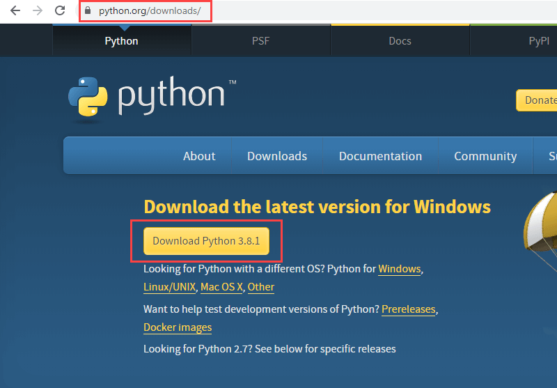
Run the downloaded Esptool installation file. As of this writing, the installation file for the latest version is python-3.8.1.
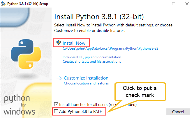
You may want to put a check mark on the Add Python 3.8 to PATH before clicking on the Install Now button. This will make it easier to start the Python and the Esptool program. Without the check mark, before you can run Python or Esptool, you would need to find the directory where you installed Python. You then would have to change your current directory to the Python’s folder.
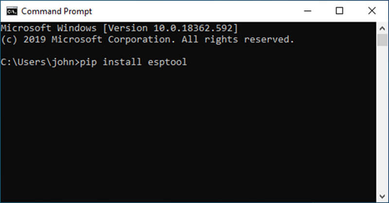
After successfully installing Python, open a command prompt window.
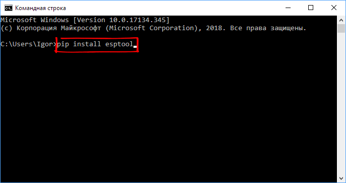
Type cmd on the Windows search box and click on the Command Prompt app. Then type the command pip install esptool.
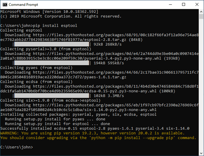
A successful Esptool installation will look like the screenshot below.
Testing the Esptool Installation
A quick test of the Esptool installation can be done by issuing the command esptool.py version.
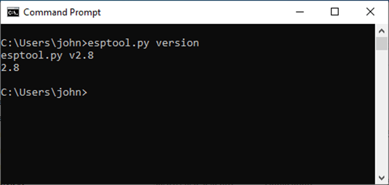
Congratulations! You now have Esptool installed and ready for use on your ESP8266 or ESP32 development board.
Examples of Possible Uses
|
esptool.py read_flash 0 0x400000 firmware_backup.bin |
Related Articles on How to Install Esptool on Windows 10
How to Install Arduino IDE on Windows 10
How to Set up Arduino IDE for ESP8266 Programming
How to Test NodeMCU V3 Using Esptool
NodeMCU V3 ESP8266 Pinout and Configuration
NodeMCU ESP-32S Pin Configuration
References on How to Install Esptool on Windows 10
Esptool Wiki on Github
Python on Wikipedia
Python Website

Данное ПО используется для прошивки устройств, собранных на чипах серии ESP82xx.
Для работы этого ПО нужен компьютер с Windows (у меня windows 10 x64) и USB-TTL адаптер( я использую на чипе CH340).
Покупал я адаптер на aliexpress:

Сначала устанавливаем драйвер адаптера. Windows 10 установила его автоматически. После удачной установки в диспетчере устройств адаптер должен выглядеть так:

Запоминаем, на каком порту висит адаптер. Позже нам это пригодится. У меня он на COM4.
Далее устанавливаем прошивальщик esptool для Windows. Для этого заходим по ссылке и скачиваем последнюю версию (на момент написания статьи это версия 3.8.0):

Запускаем скачанный файл python-3.8.0.exe:
На вопрос о способе инсталляции выбираем Customize installation:

Жмем Next:

Нажимаем Browse:

Выбираем папку для инсталляции и нажимаем Next. Путь к папке не должен содержать кириллицы:

Идет процесс инсталляции:

После успешной инсталляции видим:
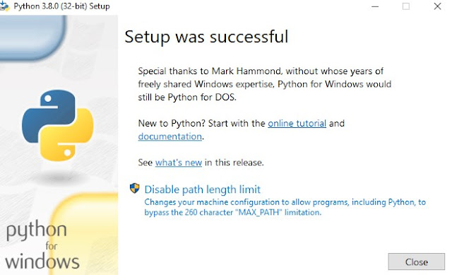
Нажимаем Close.
Установка выполнена. Нажимаем Close:

Запускаем командную строку от имени администратора и переходим в Scripts, которая находится в папке с установленной программой. Для этого в командной строке (в моем случае) нужно ввести команды
d:
cd D:SoftPythonScripts

Устанавливаем esptool, для этого вводим команду pip install esptool , жмем ENTER и ждем окончания установки программы:

После успешной установки в папке D:SoftPythonScripts должна появиться программа esptool.py.exe :

На этом установка ПО для прошивки модулей типа SONOFF закончена. Сохранение старой прошивки и установка новой будет описана позже.
esptool.py
A cute Python utility to communicate with the ROM bootloader in Espressif ESP8266.
It is intended to be a simple, platform independent, open source replacement for XTCOM.

Installation / dependencies
Easy Installation
You will need Python 2.7 or newer installed on your system.
The latest stable esptool.py release can be installed from pypi via pip:
With some Python installations this may not work and you’ll receive an error, try python -m pip install esptool or pip2 install esptool.
After installing, you will have esptool.py installed into the default Python executables directory and you should be able to run it with the command esptool.py.
Manual Installation
Manual installation allows you to run the latest development version from this repository.
esptool.py depends on pySerial for serial communication with the target device.
If you choose to install esptool.py system-wide by running python setup.py install, then this will be taken care of automatically.
If not using setup.py, then you’ll have to install pySerial manually by running something like pip install pyserial, easy_install pyserial or apt-get install python-serial, depending on your platform. (The official pySerial installation instructions are here).
Usage
Use esptool.py -h to see a summary of all available commands and command line options.
To see all options for a particular command, append -h to the command name. ie esptool.py write_flash -h.
Common Options
Serial Port
The serial port is selected using the -p option, like -p /dev/ttyUSB0 (on unixen like Linux and OSX) or -p COM1
(on Windows).
If using Cygwin on Windows, you have to convert the Windows-style name into an Unix-style path (COM1 -> /dev/ttyS0, and so on).
Baud rate
The default esptool.py baud rate is 115200bps. Different rates may be set using -b 921600 (or another baudrate of your choice). Baudrate can also be specified using ESPTOOL_BAUD environment variable. This can speed up write_flash and read_flash operations.
The baud rate is limited to 115200 when esptool.py establishes the initial connection, higher speeds are only used for data transfers.
Most hardware configurations will work with -b 230400, some with -b 460800, -b 921600 and/or -b 1500000 or higher.
If you have connectivity problems then you can also set baud rates below 115200. You can also choose 74880, which is the usual baud rate used by the ESP8266 to output boot log information.
Commands
Convert ELF to Binary
The elf2image command converts an ELF file (from compiler/linker output) into the binary blobs to be flashed:
esptool.py elf2image my_app.elf
This command does not require a serial connection.
The default command output is two binary files: my_app.elf-0x00000.bin and my_app.elf-0x40000.bin. You can alter the firmware file name prefix using the --output/-o option.
elf2image can also produce a «version 2» image file suitable for use with a software bootloader stub such as rboot or the Espressif bootloader program. You can’t flash a «version 2» image without also flashing a suitable bootloader.
esptool.py elf2image --version=2 -o my_app-ota.bin my_app.elf
Writing binaries to flash
The binaries from elf2image or make_image can be sent to the ESP8266 via the serial write_flash command:
esptool.py write_flash 0x00000 my_app.elf-0x00000.bin 0x40000 my_app.elf-0x40000.bin
Or, for a «version 2» image, a single argument:
esptool.py write_flash 0x2000 my_app-ota.bin
The arguments are one or more pairs of offset (address) and file name. The file names created by elf2image include the flash offsets for version 1. For version 2, the bootloader and linker script you are using determines the flash offset.
See the Flash Modes and Troubleshooting sections for more useful information about this command.
Verifying flash
You can verify an image in the flash by passing the --verify option to the write_flash command, or by using the standalone verify_flash command:
./esptool.py verify_flash 0x40000 my_app.elf-0x40000.bin
Verification is not always necessary, the bootloader serial protocol includes a checksum and this is usually enough to guarantee accurate flashing.
NOTE: esptool.py may update the first 16 bytes (offset 0) of the ESP8266 flash when writing (see Flash modes), to set the provided flash mode and flash size parameters. If this happens then the standalone verify_flash command may fail on these bytes (write_flash --verify accounts for this).
Manually assembling a firmware image
You can also manually assemble a firmware image from binary segments (such as those extracted from objcopy), like this:
esptool.py make_image -f app.text.bin -a 0x40100000 -f app.data.bin -a 0x3ffe8000 -f app.rodata.bin -a 0x3ffe8c00 app.flash.bin
This command does not require a serial connection.
Dumping Memory
The dump_mem command will dump a region from the ESP8266 memory space. For example, to dump the ROM (64 KiB) from the chip:
esptool.py dump_mem 0x40000000 65536 iram0.bin
Read built-in MAC address
Read SPI flash id
Refer to flashrom source code for flash chip manufacturer name and part number.
Read internal chip id:
This is the same as the output of the system_get_chip_id() SDK function. The chip ID is four bytes long, the lower three bytes are the final bytes of the MAC address. The upper byte is zero on most (all?) ESP8266s.
Serial Connections
The ESP8266 ROM serial bootloader uses a 3.3V UART serial connection. Many ESP8266 development boards make the serial connections for you onboard.
However, if you are wiring the ESP8266 yourself to a USB/Serial adapter or similar then the following connections must be made:
| ESP8266 Pin | Serial Port Pin |
|---|---|
| TX (aka GPIO1) | RX (receive) |
| RX (aka GPIO3) | TX (transmit) |
| Ground | Ground |
Note that TX (transmit) on the ESP8266 is connected to RX (receive) on the serial port connection, and vice versa.
Do not connect the ESP8266 to 5V TTL serial adapters, and especially not to high voltage RS-232 adapters! 3.3v serial only!
Entering the Bootloader
The ESP8266 has to be reset in a certain way in order to launch the serial bootloader.
On some development boards (including NodeMCU, WeMOS, HUZZAH Feather), esptool.py can automatically trigger a reset into the serial bootloader — in which case you don’t need to read this section.
For everyone else, three things must happen to enter the serial bootloader — a reset, required pins set correctly, and GPIO0 pulled low:
Reset
The ESP8266 chooses the boot mode each time it resets. A reset event can happen in one of several ways:
- Power applied to ESP8266.
- The nRESET pin was low and is pulled high.
- The CH_PD pin («enable») was low and is pulled high.
The nRESET and ENABLE pins must both be pulled high.
Required Pins
The following ESP8266 pins must be pulled high/low for either normal or serial bootloader operation. Most development boards or modules make these connections already, internally:
| GPIO | Must Be Pulled |
|---|---|
| 15 | Low/GND (directly, or with a resistor) |
| 2 | High/VCC (always use a resistor) |
If these pins are set differently to shown, nothing on the ESP8266 will work as expected. See this wiki page to see what boot modes are enabled for different pin combinations.
GPIO2 should always use a pullup resistor to VCC, not a direct connection. This is because it is configured as an output by the boot ROM. If GPIO15 is unused then it can be connected directly to ground, but it’s safest to use a pulldown resistor here as well.
Selecting bootloader mode
The ESP8266 will enter the serial bootloader when GPIO0 is held low on reset. Otherwise it will run the program in flash.
| GPIO0 Input | Mode |
|---|---|
| Low/GND | ROM serial bootloader for esptool.py |
| High/VCC | Normal execution mode |
Many configurations use a «Flash» button that pulls GPIO0 low when pressed.
Automatic bootloader
esptool.py can automatically enter the bootloader on many boards by using only the RTS and DTR modem status lines.
Make the following connections for esptool.py to automatically enter the bootloader:
| ESP8266 Pin | Serial Pin |
|---|---|
| CH_PD («enable») or nRESET | RTS |
| GPIO0 | DTR |
Note that some serial terminal programs (not esptool.py) will assert both RTS and DTR when opening the serial port, pulling them low together and holding the ESP8266 in reset. If you’ve wired RTS to the ESP8266 then you should disable RTS/CTS «hardware flow control» in the program. Development boards like NodeMCU use additional circuitry to avoid this problem — if both RTS and DTR are asserted together, this doesn’t reset the chip.
Flash Modes
write_flash and some other comands accept command line arguments to set flash mode, flash size and flash clock frequency. The ESP8266 needs correct mode, frequency and size settings in order to run correctly — although there is some flexibility.
When flashing at offset 0x0, the first sector of the ESP8266 flash is updated automatically using the arguments passed in.
Flash Mode (—flash_mode, -fm)
These set Quad Flash I/O or Dual Flash I/O modes. Valid values are qio, qout, dio, dout. The default is qio. This parameter can also be specified using the environment variable ESPTOOL_FM.
Some ESP8266 modules, including the ESP-12E modules on some (not all) NodeMCU boards, are dual I/O and will only work with --flash_mode dio.
In qio mode, GPIOs 9 and 10 are used for SPI flash communications. If flash mode is set to dio then these pins are available for other purposes.
Flash Size (—flash_size, -fs)
Size of the SPI flash. Valid values are 4m, 2m, 8m, 16m, 32m, 16m-c1, 32m-c1, 32m-c2 (megabits). The default is 4m (4 megabits, 512 kilobytes.) This parameter can also be specified using the environment variable ESPTOOL_FS.
The ESP8266 SDK stores WiFi configuration at the «end» of flash, and it finds the end using this size. However there is no downside to specifying a smaller flash size than you really have, as long as you don’t need to write an image larger than the configured size.
ESP-12, ESP-12E and ESP-12F modules (and boards that use them such as NodeMCU, HUZZAH, etc.) usually have at least 32 megabit (32m i.e. 4MB) flash. You can find the flash size by using the flash_id command and then looking up the ID from the output (see Read SPI flash id).
Flash Frequency (—flash_freq, -ff)
Clock frequency for SPI flash interactions. Valid values are 40m, 26m, 20m, 80m (MHz). The default is 40m (40MHz). This parameter can also be specified using the environment variable ESPTOOL_FF.
The flash chip on most ESP8266 modules works with 40MHz clock speeds, but you can try lower values if the device won’t boot.
Troubleshooting
ESP8266 problems can be fiddly to troubleshoot. Try the suggestions here if you’re having problems:
Bootloader won’t respond
If you see errors like «Failed to connect to ESP8266» then your ESP8266 is probably not entering the bootloader properly:
- Check you are passing the correct serial port on the command line.
- Check you have permissions to access the serial port, and other software (such as modem-manager on Linux) is not trying to interact with it.
- Check the ESP8266 is receiving 3.3V from a stable power source (see Insufficient Power for more details.)
- Check that all pins are connected as described in Entering the bootloader. Check the voltages at each pin with a multimeter, «high» pins should be close to 3.3V and «low» pins should be close to 0V.
- If you have connected other devices to GPIO0, GPIO2 or GPIO15 then try removing them and see if esptool.py starts working.
- Try using a slower baud rate (
-b 9600is a very slow value that you can use to verify it’s not a baud rate problem.)
write_flash operation fails part way through
If flashing fails with random errors part way through, retry with a lower baud rate.
Power stability problems may also cause tihs (see Insufficient Power.)
write_flash succeeds but ESP8266 doesn’t run
If esptool.py can flash your module with write_flash but your program doesn’t run, try the following:
Wrong Flash Mode
Some ESP8266 modules only support the dio flash mode. Writing to flash with qio mode will succeed but the ESP8266 can’t read it back to run — so nothing happens on boot. Try passing the -fm dio option to write_flash.
Insufficient Power
The 3.3V power supply for the ESP8266 has to supply large amounts of current (up to 70mA continuous, 200-300mA peak). You also need sufficient capacitance on the power circuit to meet large spikes of power demand.
If you’re using a premade development board or module then the built-in power regulator is usually good enough, provided the input power supply is adequate.
It is possible to have a power supply that supplies enough current for the serial bootloader stage with esptool.py, but not enough for normal firmware operation. You may see the 3.3V VCC voltage droop down if you measure it with a multimeter, but you can have problems even if this isn’t happening.
Try swapping in a 3.3V supply with a higher current rating, add capacitors to the power line, and/or shorten any 3.3V power wires.
The 3.3V output from FTDI FT232R chips/adapters or Arduino boards do not supply sufficient current to power an ESP8266 (it may seem to work sometimes, but it won’t work reliably).
Missing bootloader
Recent Espressif SDKs use a small firmware bootloader program. The hardware bootloader in ROM loads this firmware bootloader from flash, and then it runs the program. This firmware bootloader image (with a filename like boot_v1.x.bin) has to be flashed at offset 0. If the firmware bootloader is missing then the ESP8266 will not boot.
Refer to your SDK documentation for details regarding which binaries need to be flashed at which offsets.
SPI Pins which must be disconnected
Compared to the ROM bootloader that esptool.py talks to, a running firmware uses more of the ESP8266’s pins to access the SPI flash.
If you set «Quad I/O» mode (-fm qio, the esptool.py default) then GPIOs 7, 8, 9 & 10 are used for reading the SPI flash and must be otherwise disconnected.
If you set «Dual I/O» mode (-fm dio) then GPIOs 7 & 8 are used for reading the SPI flash and must be otherwise disconnected.
Try disconnecting anything from those pins (and/or swap to Dual I/O mode if you were previously using Quad I/O mode but want to attach things to GPIOs 9 & 10).
In addition to these pins, GPIOs 6 & 11 are also used to access the SPI flash (in all modes). However flashing will usually fail completely if these pins are connected incorrectly.
Early stage crash
Use a serial terminal program to view the boot log at 74880bps, see if the program is crashing during early startup or outputting an error message. See Boot log for an example.
Serial Terminal Programs
There are many serial terminal programs suitable for normal ESP8266 debugging & serial interaction. The pyserial module (which is required for esptool.py) includes one such command line terminal program — miniterm.py. For more details see this page or run miniterm -h.
Note that not every serial program supports the unusual ESP8266 74880bps «boot log» baud rate. Support is especially sparse on Linux. miniterm.py supports this baud rate on all platforms.
Internal Technical Documentation
The repository wiki contains some technical documentation regarding the serial protocol and file format used by the ROM bootloader. This may be useful if you’re developing esptool.py or hacking system internals:
- Firmware Image Format
- Serial Protocol
Boot log
The boot rom writes a log to the UART when booting. The timing is a little bit unusual: 74880 baud
ets Jan  8 2014,rst cause 1, boot mode:(3,7)

load 0x40100000, len 24236, room 16
tail 12
chksum 0xb7
ho 0 tail 12 room 4
load 0x3ffe8000, len 3008, room 12
tail 4
chksum 0x2c
load 0x3ffe8bc0, len 4816, room 4
tail 12
chksum 0x46
csum 0x46
About
esptool.py was initially created by Fredrik Ahlberg (themadinventor, kongo), and is currently maintained by Fredrik and Angus Gratton (@projectgus). It has also received improvements from many members of the ESP8266 community — including pfalcon, tommie, 0ff and george-hopkins.
This document and the attached source code is released under GPLv2.
Содержание
Утилита Esptool поможет считать и записать на платформу с чипом ESP8266EX прошивку в формате .bin.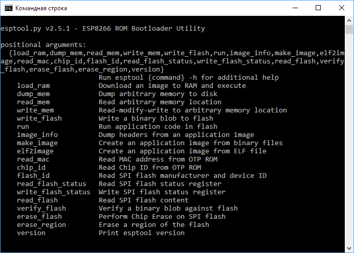
Подготовка железа
Подключите управляющую платформу в режиме прошивки.
-
Подключение WiFi Slot: просто подключите платформу к ПК через micro-USB разъём;
Установка ПО
-
Скачайте и установите последнюю версию интерпретатора с официального сайта Python.
При установке поставьте галочку в пункте «Add python.exe to PTH». -
Зайдите в командную строку: :
-
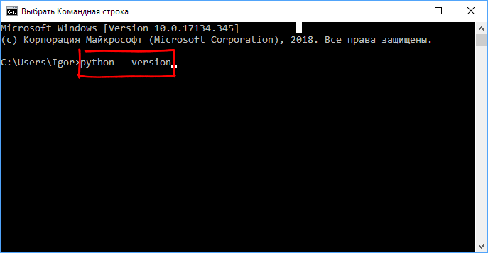
Проверьте установленную версию Python. Введите в командной строке:
python --version
В ответ консоль выдаст строку с версией Python.
-
Установите через менеджер пакетов pip утилиту esptool.
pip install esptool
-
Узнайте установленную версию Esptool.
esptool.py version
В ответ командная строка выдаст ответ с текущей версией утилиты.Это значит, что утилита установилась и можно переходить к чтению или записи прошивки.
 При установке поставьте галочку в пункте «Add python.exe to PTH».
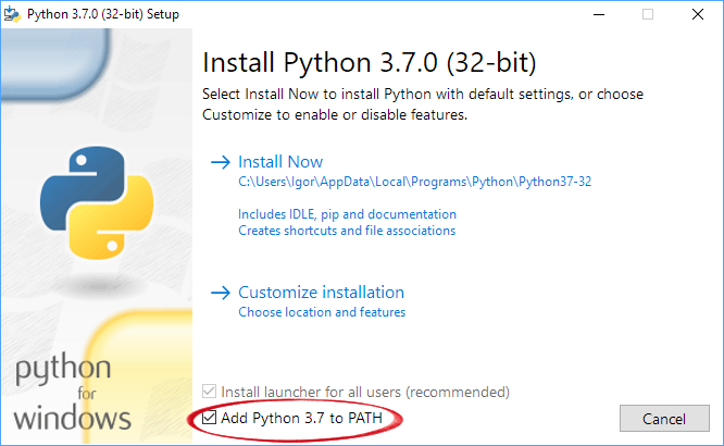
 В ответ консоль выдаст строку с версией Python.
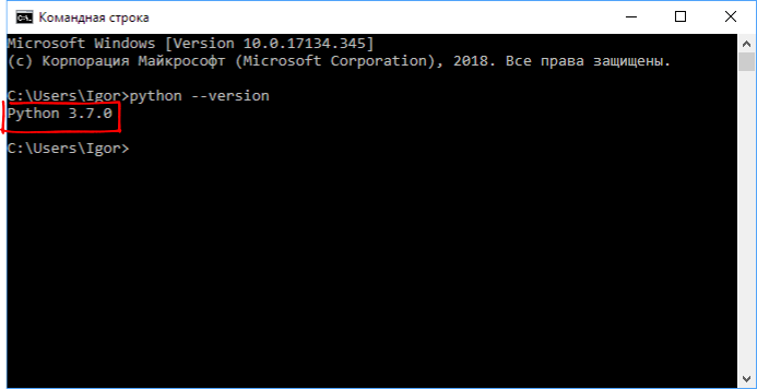
 В ответ командная строка выдаст ответ с текущей версией утилиты.
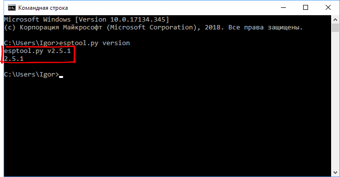 Это значит, что утилита установилась и можно переходить к чтению или записи прошивки.
Чтение прошивки
-
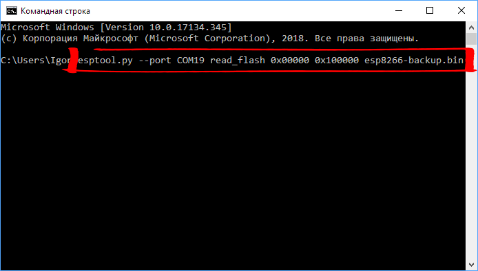
Для чтение прошивки необходимо вбить в консоль строку с определёнными параметрами. В зависимости от модуля и других факторов параметры команды отличаются. Рассмотрим на примере строки:
esptool.py --port COM19 read_flash 0x00000 0x100000 esp8266-backup.bin
-
esptool.py— запуск утилиты; -
–port COM19— номер COM-порта устройства. Узнайте ваш номер в диспетчере задач; -
read_flash— команда считывания данных из флэш-памяти; -
0x00000— адрес начала считывания флэш-памяти; -
0x10000— адрес конца считывания флэш-памяти; -
esp8266-backup.bin— имя файла для считываемой прошивки.
-
-
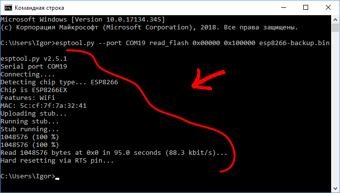
Со строкой разобрались. Пора считывать.
В ответ начнётся считывание прошивки с модуля с индикацией состояния в консоле.
-
Дождитесь окончания прошивки.
-
Файл прошивки вы найдёте в директории из которой работали в командной строке. Теперь можно прошивать модули на чипе ESP8266 любой кастомной прошивкой.
Для возврата к заводской прошивки воспользуйтесь утилитой esptool.
 В ответ начнётся считывание прошивки с модуля с индикацией состояния в консоле.
Быстро установим esptool в Windows 10 и научимся базовым командам
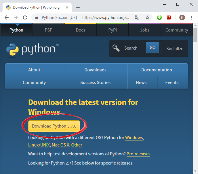
Так как esptool написана на языке программирования Python, то нам нужно установить одноименную версию софта для работы в Windows. Скачиваем по ссылке.

На момент написания это версия 3.8.2
Теперь устанавливаем, отметив галочкой Add Python 3.8 to PATH

Пол дела сделано. Проверить корректность установки можно введя в командой строке команду:
python --version
В ответ получим:

Теперь о самой esptool. Ставим ее командой:
pip install esptool
Начнется установка:


Теперь можно пользоваться утилитой. Подключаем esp8266 к компьютеру и смотрим COM порт в Диспетчере устройств:

В данном случае это COM3. И можно пользоваться. Узнать все доступные команды можно набрав:
esptool.py -h
Например, чтобы узнать версию подключенной esp, вводим команду:
esptool.py -p COM3 -b 115200 flash_id
В ответ получим всю информацию:

Чтобы сделать бэкап прошивки с 4мб памяти:
esptool.py -p COM3 -b 115200 read_flash 0x00000 0x400000 backup.bin
Полностью стереть прошивку:
esptool.py -p COM3 -b 115200 erase_flash
Или, например, чтобы залить прошивку:
esptool.py -p COM3 -b 115200 --after no_reset write_flash --flash_size 4MB --flash_mode dio 0x00000 firmware.bin --erase-all
5
9
голоса
Рейтинг статьи
This post shows how to flash MicroPython firmware on ESP32/ESP8266 boards using the esptool.py. It works on Windows, Mac OS X, and Linux. For the official documentation, you can visit the esptool.py GitHub page.

Tip: for an easier method to flash the ESP32/ESP8266 with MicroPython, we recommend reading this guide to flash MicroPython with uPyCraft IDE. However, we’ve recently received comments from our readers about having trouble installing/using uPyCraft IDE. For that reason, we’re posting an alternative method using the esptool.py software.
Installing esptool.py in your computer
To work with esptool.py, you’ll need either Python 2.7, Python 3.4 or a newer Python installation on your system. We recommend using Python 3.7.X, so go to Python’s website and install it on your computer.
With Python 3 installed, open a Terminal window and install the latest stable esptool.py release with pip:
pip install esptool
Note: with some Python installations that command may not work and you’ll receive an error. If that’s the case, try to install esptool.py with:
- pip3 install esptool
- python -m pip install esptool
- pip2 install esptool
Setuptools is also a requirement that is not available on all systems by default. You can install it with the following command:
pip install setuptoolsAfter installing, you will have esptool.py installed into the default Python executables directory and you should be able to run it with the command esptool.py. In your Terminal window, run the following command:
python -m esptool
If it was installed properly, it should display a similar message (regardless of your operating system):

With esptool.py installed on your computer, you can easily flash your ESP32 or ESP8266 boards with the MicroPython firmware. This post is divided into two parts, read Part 1 or Part 2 depending on your board:
- Part 1 – ESP32
- Part 2 – ESP8266
Note: after installing MicroPython firmware on your ESP32 or ESP8266, you can go back and use Arduino IDE again. You just need to upload code using Arduino IDE. Then, if you want to use MicroPython again, you need to flash MicroPython firmware.
[Part 1 – ESP32] Downloading and Flashing the MicroPython Firmware on ESP32
To download the latest version of MicroPython firmware for the ESP32, go to the MicroPython Downloads page and scroll all the way down to the ESP32 section.
You should see a similar web page (see figure below) with links to download .bin files. Download the latest release. At the time of writing this article, the latest release is v1.17 (2021-02-02).bin. Don’t download the Nighlty builds; those versions are not stable and are only recommended for advanced programmers.

Note: if you’re using a different board (like a PyBoard, WiPy, or other), go to MicroPython Downloads page and download the right firmware for your board.
Finding the Serial Port Name
It’s a bit different to find the Serial port name in each operating system, so for simplicity reasons we recommend finding your ESP serial port name through the Arduino IDE. Follow these steps:
- Connect your board to your computer
- Open the Arduino IDE
- Go to Tools > Port
- Save your ESP32 serial port name (in our case it’s COM7)
- Close your Arduino IDE software

Important: if you plug your ESP32 board into your computer, but you can’t find the ESP32 Port available in your Arduino IDE, it might be one of these two problems: 1. USB drivers missing or 2. USB cable without data wires.
1. If you don’t see your ESP’s COM port available, this often means you don’t have the USB drivers installed. Take a closer look at the chip next to the voltage regulator on board and check its name.
The ESP32 DEVKIT V1 DOIT board uses the CP2102 chip.

Go to Google and search for your specific chip to find the drivers and install them in your operating system.

You can download the CP2102 drivers on the Silicon Labs website.

After they are installed, restart the Arduino IDE and you should see the serial port in the Tools > Port menu.
2. If you have the drivers installed, but you can’t see your device, double-check that you’re using a USB cable with data wires.
USB cables from powerbanks often don’t have data wires (they are charge only). So, your computer will never establish a serial communication with your ESP32. Using a proper USB cable should solve your problem.
Finding your MicroPython .bin file
After downloading the ESP32 .bin file, it should be in your Downloads folder. So, with your Terminal window, you’ll need to navigate to the Downloads folder using the cd command:
cd Downloads

List all files in your Downloads folder to ensure that’s where the .bin file is located. In Windows, you use:
dir
On Mac OS X or Linux, run the next command:
ls

As you can see in the preceding screenshot, the ESP32 .bin file is located in the Downloads folder: esp32-20190113-v1.9.4-779-g5064df207.bin.
Erasing ESP32 Flash Memory
Before flashing the MicroPython firmware, you need to erase the ESP32 flash memory. So, with your ESP32 connected to your computer, hold-down the “BOOT/FLASH” button in your ESP32 board:

While holding down the “BOOT/FLASH” button, run the following command to erase the ESP32 flash memory:
python -m esptool --chip esp32 erase_flash
When the “Erasing” process begins, you can release the “BOOT/FLASH” button. After a few seconds, the ESP32 flash memory will be erased.

Note: if after the “Connecting …” message you keep seeing new dots appearing, it means that your ESP32 is not in flashing mode. You need to repeat all the steps described earlier and hold the “BOOT/FLASH” button again to ensure that your ESP32 goes into flashing mode and completes the erasing process successfully.

Flashing MicroPython Firmware on ESP32 with esptool.py
With your ESP32 flash memory erased, you can finally flash the MicroPython firmware. You need your serial port name (COM7 in our case) and the ESP32 .bin file location. Replace the next command with your details:
python -m esptool --chip esp32 --port <serial_port> write_flash -z 0x1000 <esp32-X.bin>
In our case, the command looks like this:
python -m esptool --chip esp32 --port COM7 write_flash -z 0x1000 esp32-20190113-v1.9.4-779-g5064df207.bin
Hold down the “BOOT/FLASH“, before running the flash command. After a few seconds this is what you should see:

Your ESP32 was successfully flashed with MicroPython firmware!
Note: if you receive an error trying to flash the firmware, run the command again and make sure you are holding down the ESP32 “BOOT/FLASH” button.

[Part 2 – ESP8266] Downloading and Flashing the MicroPython Firmware on ESP8266
To download the latest version of MicroPython firmware for the ESP32, go to the MicroPython Downloads page and scroll all the way down to the ESP8266 section.
You should see a similar web page (see figure below) with links to download .bin files. Download the latest release. At the time of writing this article, the latest release is v1.17 (2021-02-02).bin. Don’t download the Nighlty builds; those versions are not stable and are only recommended for advanced programmers.
Note: if you’re using a different board (like a PyBoard, WiPy, or other), go to MicroPython Downloads page and download the right firmware for your board.
Finding the Serial Port Name
It’s a bit different to find the Serial port name in each operating system, so for simplicity reasons we recommend finding your ESP serial port name through the Arduino IDE. Follow these steps:
- Connect your board to your computer
- Open the Arduino IDE
- Go to Tools > Port
- Save your ESP8266 serial port name (in our case it’s COM4)
- Close your Arduino IDE software

Important: if you plug your ESP8266 board to your computer, but you can’t find the ESP8266 Port available in your Arduino, it might be one of these two problems: 1. USB drivers missing or 2. USB cable without data wires.
1. If you don’t see your ESP’s COM port available, this often means you don’t have the USB drivers installed. Take a closer look at the chip next to the voltage regulator on board and check its name.
The ESP8266 ESP-12E NodeMCU board uses the CP2102 chip.

Go to Google and search for your specific chip to find the drivers and install them in your operating system.
You can download the CP2102 drivers on the Silicon Labs website.
After they are installed, restart the Arduino IDE and you should see the serial port in the Tools > Port menu.
2. If you have the drivers installed, but you can’t see your device, double-check that you’re using a USB cable with data wires.
USB cables from powerbanks often don’t have data wires (they are charge only). So, your computer will never establish a serial communication with your ESP8266. Using a proper USB cable should solve your problem.
Finding your MicroPython .bin file
After downloading the ESP8266 .bin file, it should be in your Downloads folder. So, with your Terminal window, you’ll need to navigate to the Downloads folder using the cd command:
cd Downloads
List all files in your Downloads folder to ensure that’s where the .bin file is located. In Windows, you use:
dir
On Mac OS X or Linux, run the next command:
ls
As you can see in the preceding screenshot, the ESP8266 .bin file is located in the Downloads folder: esp8266-20180511-v1.9.4.bin.
Erasing ESP8266 Flash Memory
Before flashing the MicroPython firmware, you need to erase the ESP8266 flash memory. So, with your ESP8266 connected to your computer, hold-down the “BOOT/FLASH” button in your ESP8266 board:

While holding down the “BOOT/FLASH” button, run the following command to erase the ESP8266 flash memory:
python -m esptool --chip esp8266 erase_flash
When the “Erasing” process begins, you can release the “BOOT/FLASH” button. After a few seconds, the ESP8266 flash memory will be erased.

Note: if after the “Connecting …” message you keep seeing new dots appearing, it means that your ESP8266 is not in flashing mode. You need to repeat all the steps described earlier and hold the “BOOT/FLASH” button again to ensure that your ESP8266 goes into flashing mode and completes the erasing process successfully.
Flashing MicroPython Firmware on ESP8266 with esptool.py
With your ESP8266 flash memory erased, you can finally flash the MicroPython firmware. You need your serial port name (COM7 in our case) and the ESP8266 .bin file location. Replace the next command with your details:
python -m esptool --chip esp8266 --port <serial_port> write_flash --flash_mode dio --flash_size detect 0x0 <esp8266-X.bin>
In our case, the final command looks like this:
python -m esptool --chip esp8266 --port COM4 write_flash --flash_mode dio --flash_size detect 0x0 esp8266-20180511-v1.9.4.bin
Hold down the “BOOT/FLASH“, before running the flash command. After a few seconds this is what you should see:

Your ESP8266 was successfully flashed with MicroPython firmware!
Note: if you receive an error trying to flash the firmware, run the command again and make sure you are holding down the ESP8266 “BOOT/FLASH” button.
Wrapping Up
We hope you’ve found this tutorial useful. Your ESP32/ESP8266 should now be flashed with MicroPython firmware. To learn more about MicroPython read: Getting Started with MicroPython on ESP32 and ESP8266.
If you liked this post, you might like our next ones, so make sure you subscribe to the RNT blog and download our free electronics eBooks.