В этой статье мы покажем, как настроить тегированный сетевой интерфейс с VLAN в Windows 10/11 и Windows Server 2019 (2022/2016/2012R2). Стандарт VLAN (Virtual LAN) описан в 802.1Q и предполагает маркировку трафика с помощью тегов (vlanid), необходимую для отнесения сетевого пакета к той или иной виртуальной сети. VLAN используются для разделения и сегментирования сетей, ограничения широковещательных доменов и изоляции сегментов сети для повышения безопасности. В Windows вы можете настроить несколько логических сетевых интерфейсов с разными номерами VLAN на одном физическом интерфейсе несколькими способами.
Содержание:
- Настройка VLAN интерфейсов в Windows 10 и 11
- Добавить несколько VLAN ID в Windows Server 2019/2016
- Как создать несколько VLAN в Windows Hyper-V?
Для использования VLAN необходимо соответствующим образом перенастроить порт коммутатора, куда подключен ваш компьютер/сервер. Порт должен быть переведен из режима access в режим транк. По умолчанию на транк порту разрешены все VLAN, но вы можете указать список номеров разрешенных VLAN(от 1до 4094), которые доступны на данном порту коммутатора Ethernet.
Настройка VLAN интерфейсов в Windows 10 и 11
В десктопных версиях Windows нет встроенный поддержки VLAN. По умолчанию драйвера большинства сетевых адаптеров обрезают в пакетах все VLAN-тэги и внешние VLAN становиться недоступными.
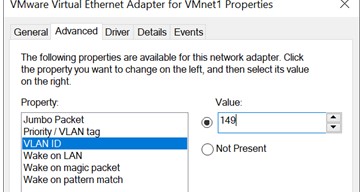
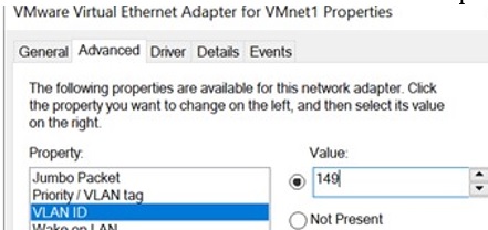
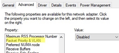
Для некоторых сетевых адаптеров вы можете задать номер VLAN в настройках драйвера:
- Запустите консоль диспетчера устройств (
devmgmt.msc
); - Разверните секцию Network adapters и откройте свойства вашего сетевого адаптера;
- Перейдите на вкладку Advanced и найдите опцию VLAN ID;

- Здесь вы можете задать номер VLAN;
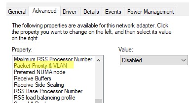
- У некоторых сетевых карт сначала нужно включить опцию Packet Priority and VLAN.

В современных версиях Windows 10 и 11 вы можете задать один тег VLAN для вашего сетевого интерфейса. Для этого используется командлет PowerShell для управления сетевыми настройками. Например, вы хотите задать VLAN 50 для вашего сетевого интерфейса с именем Ethernet1:
Set-NetAdapter –Name "Ethernet1" -VlanID 50
Для некоторых сетевых карт (Intel, Broadcom, HP, Realtek) доступны специальные утилиты, позволяющие создать в Windows виртуальный сетевой интерфейс с VLAN ID. Для этого на компьютере нужно установить специальный драйвер с поддержкой тегированного трафика 802.1Q и официальную утилиту от вендора.
Создаем VLAN интерфейсы в Windows 10/11 на сетевой карте Realtek
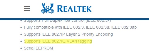
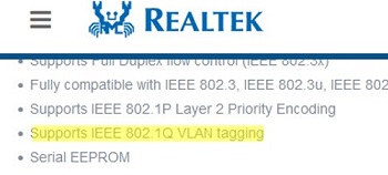
Для сетевых карт Realtek вы можете настроить несколько виртуальных сетевых адаптеров с различными VLAN с помощью утилиты Realtek Ethernet Diagnostic Utility. Найдите описание вашего сетевого контролера Realtek на сайте вендора, и проверьте что эта модель поддерживает VLAN. Например, в спецификации сетевого контроллера RTL8169SC(L) присутствует строка:
Supports IEEE 802.1Q VLAN tagging
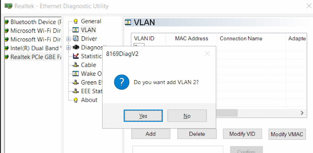
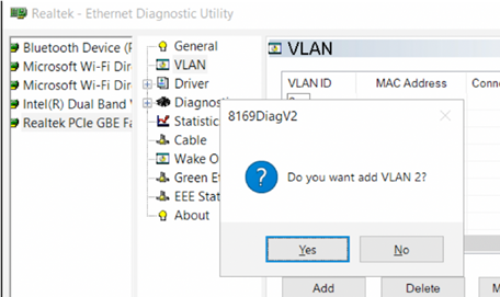
Скачайте и установите последнюю версию сетевого драйвера для вашего адаптера Realtek и запустите утилиту Realtec Ethernet Diagnostic Utility (Diagnostic Program for Win7/Win8/Win10/Win11).
Перейдите в раздел VLAN, нажмите кнопку Add и добавьте нужный VLAN ID. После этого в Windows появится новый сетевой интерфейс.
После того, как вы создали сетевые интерфейсы для ваших VLAN, вы можете задать на них нужный IP из соответствующей подсети.
Добавляем VLAN интерфейсы на сетевом адаптере Intel Ethernet
У Intel для настройки VLAN есть собственная утилита Intel Advanced Network Services (Intel® ANS) VLAN. Ваша модель сетевого адаптера, естественно, должна поддерживать технологию VLAN (например, VLAN не поддерживаются для карт Intel PRO/100 и PRO/1000). При установке драйвера выбейте опции Intel PROSet for Windows Device Manager и Advanced Network Services.
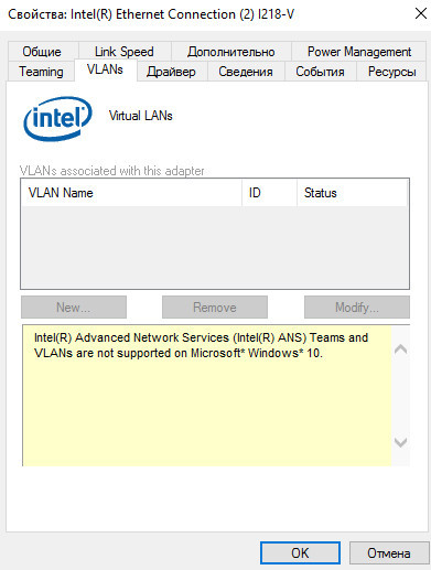
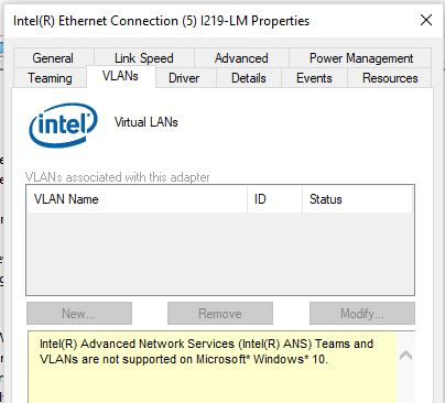
После этого в свойствах физического сетевого адаптера Intel появляется отдельная вкладка VLANs, где вы можете добавить несколько VLAN интерфейсов.
Однако этот способ работает во всех предыдущих версиях Windows (до Windows 10 1809). В последних версиях Windows на этой вкладке присутствует надпись:
Intel(R) Advanced Network (Intel(R) ANS) Teams and VLANs are not supported on Microsoft Windows 10.
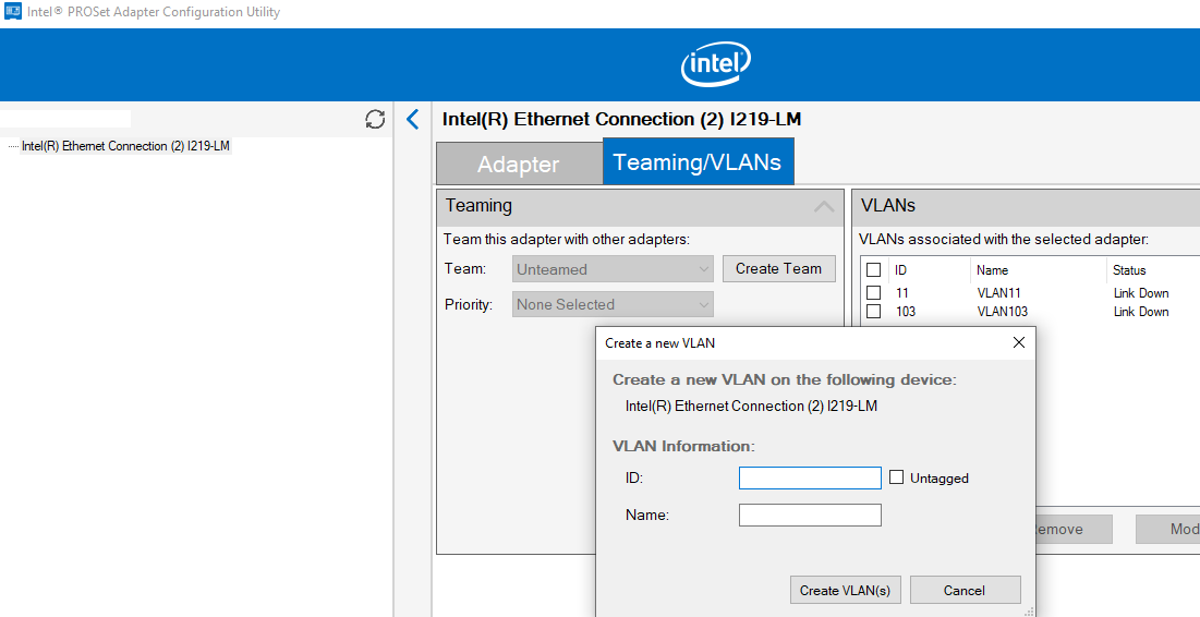
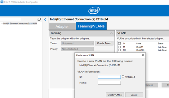
Intel недавно выпустила обновленные драйвера сетевых адаптеров и утилиту Intel PROSet Adapter Configuration Utility для последних версий Windows 10 и 11. Скачайте и установите последнюю версию драйвера Intel и утилиту Intel PROset.
Запустите утилиту, перейдите на вкладку Teaming/VLANs, нажмите кнопку New, и укажите имя сетевого интерфейса и его VLANID.
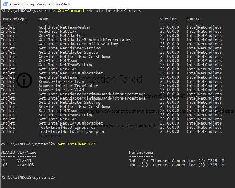
Кроме того, вы можете добавить/удалить/просмотреть список VLAN на сетевых картах Intel с помощью специальных PowerShell командлетов из модуля IntelNetCmdlets. Импортируйте модуль в свою PowerShell сессию:
Import-Module -Name "C:Program FilesIntelWired NetworkingIntelNetCmdletsIntelNetCmdlets" -Scope Local
Вы можете создать нетегированный виртуальный сетевой адаптер (обычно используется с native-vlan-id):
Add-IntelNetVLAN -ParentName "Intel(R) Ethernet Connection I219-LM" -VLANID 0
Чтобы создать сетевой адаптер Intel с конкретным номером VLAN:
Add-IntelNetVLAN -ParentName "Intel(R) Ethernet Connection I219-LM" -VLANID 11
Чтобы вывести список всех виртуальных сетевых адаптеров Intel:
Get-NetAdapter
Удалить VLAN адаптер:
Remove-IntelNetVLAN -ParentName "Intel(R) Ethernet Connection I219-LM" -VLANID 11
Для сетевых карт Broadcom вы можете создавать группы виртуальных сетевых интерфейсов и назначать им VLAN ID с помощью утилиты Broadcom Advanced Control Suite.
Добавить несколько VLAN ID в Windows Server 2019/2016
В Windows Server 2022/2019/2016/2012R2 вы можете настроить несколько VLAN на одном сетевом интерфейсе с помощью встроенных средств (без установки специальных драйверов или утилит). Попробуем настроить несколько разных VLAN на одной физической сетевой карте в Windows Server 2019 с помощью NIC Teaming.
Обязательно убедитесь, что в настройках параметров дополнительных свойств сетевого адаптера не задана VLAN (значение VLAN ID = 0). 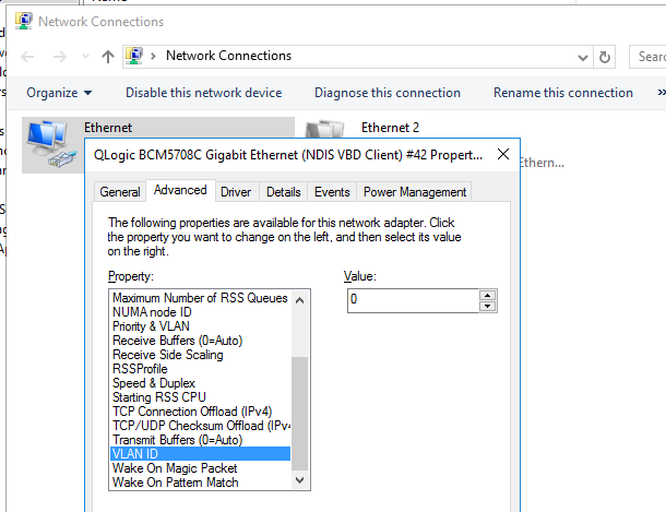
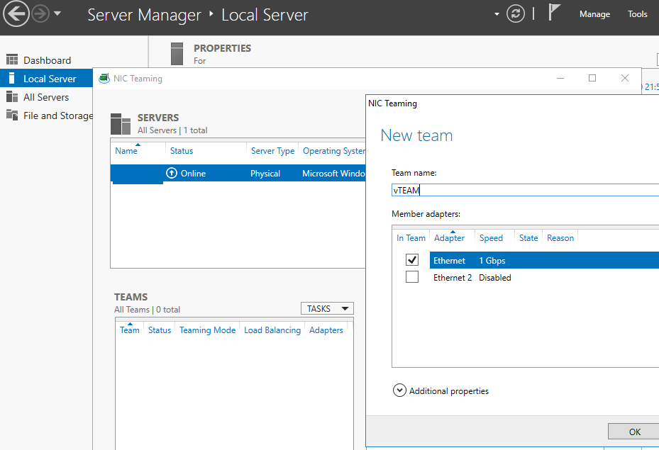
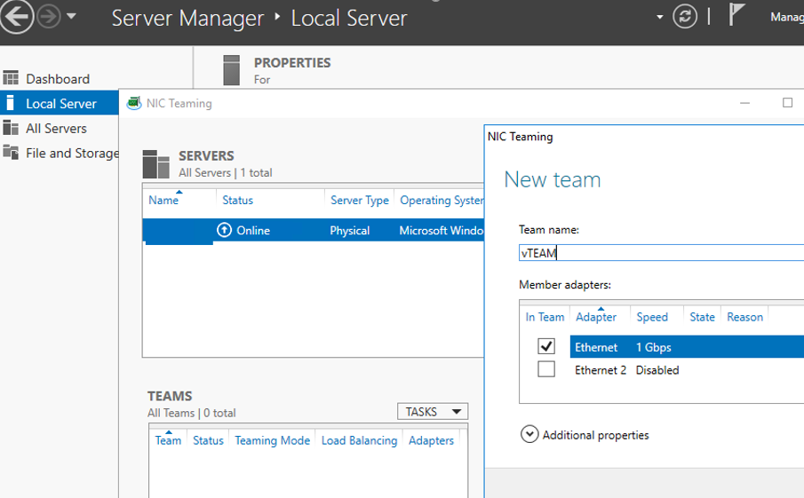
- Запустите Server Manager -> Local и нажмите на ссылку «NIC Teaming«;
- В секции Teams нажмите Task -> New Team. Укажите имя группы и выберите сетевые адаптеры, которые нужно в нее добавить;

Можно создать группу NIC Teaming с помощью PowerShell:
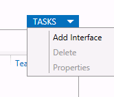
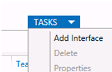
New-NetLbfoTeam -Name vTeam -TeamMembers "Ethernet1","Ethernet2" -TeamingMode SwitchIndependent -LoadBalancingAlgorithm Dynamic - Теперь в секции «Adapter and Interfaces» можно добавить виртуальные сетевые интерфейсы. Нажмите Tasks -> Add Interface;

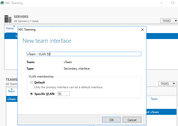
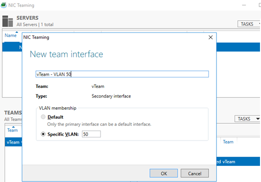
- Укажите имя создаваемого интерфейса и номер VLAN;

Из PowerShell добавить сетевой интерфейс и задать ему VLAN можно так:
Add-NetLbfoTeamNic -Team vTeam -VlanID 50 -Name VLAN50 - Аналогичным образом можно добавить столько сетевых интерфейсов VLAN, сколько нужно;
Обратите внимание, что в Windows Server 2022/2019/2016 поддерживает не более 32 сетевых адаптеров (и соответственно уникальных VLAN) для одной группы NIC Teaming.
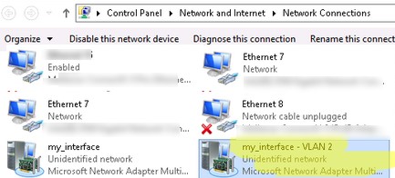
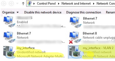
- Для каждого сетевого интерфейса в панели управления сетевыми адаптерами (ncpa.cpl) появится отдельная виртуальная сетевая карта;

- Теперь вы можете настроить IP параметры всех созданных виртуальных VALN сетевых интерфейсов вручную в свойствах адаптера или с помощью PowerShell командлетов New-NetIPAddress и Set-DnsClientServerAddress:
New-NetIPAddress -InterfaceAlias my_VLAN_interface -IPAddress 192.168.30.30 -PrefixLength 24 -DefaultGateway 192.168.30.1
Set-DnsClientServerAddress -InterfaceAlias my_VLAN_interface -ServerAddresses 192.168.1.10
Как создать несколько VLAN в Windows Hyper-V?
Вы можете программно обрабатывать VLANы в Windows через через подсистему Hyper-V (доступно как в Windows Server, так и десктопных Windows 10/11 Pro и Enterprise редакциях). Вы можете создать виртуальный свитч с сетевым адаптером в определённом VLAN.
Для этого нужно установить компоненты Hyper-V:
Enable-WindowsOptionalFeature -Online -FeatureName:Microsoft-Hyper-V -All
Создайте новый виртуальный коммутатор через Hyper-V Manager или с помощью команд PowerShell (см. пример в статье о настройке Hyper-V Server).
Затем для каждого VLAN, который нужно создать, выполнить команды:
Add-VMNetworkAdapter -ManagementOS -Name VLAN50 -StaticMacAddress "11-22-33-44-55-AA" -SwitchName VLAN50Switch
Set-VMNetworkAdapterVlan -ManagementOS -VMNetworkAdapterName VLAN50 -Access -VlanId 50
В результате у вас в системе появится сетевой адаптер с нужным тегом VLAN.
Если на вашем Hyper-V сервере запущены ВМ, вы можете поместить их в разные VALN. Чтобы переключить виртуальны сетевой адаптер ВМ на Hyper-V в режим Access и разрешить получать трафик только с определенным VLAN ID, используется команда:
Set-VMNetworkAdapterVlan -VMName Test1 -Access -VlanId 21
Вывести список ВМ и назначенных им VLAN:
Get-VMNetworkAdapterVLAN
В Windows Server 2022 с ролью Hyper-V вы не сможете привязать виртуальный свитч к такому тиминг-интерфейсу. Дело в том, что что LBFO NIC Teaming устарел (https://aka.ms/lbfodeprecation) и в Windows Server 2022 предлагается использовать Switch Embedded Teaming (SET).
Рассмотрим, как создать виртуальный адаптер и назначить ему VLAN в Windows Server 2022 Hyper-V с помощью SET.
Создайте виртуальный свитч, подключённый к сетевым адаптерам хоста:
New-VMSwitch -Name "HVSwitch1" -NetAdapterName "Ethernet3","Ethernet4" -EnableEmbeddedTeaming $true
Теперь создайте виртуальны адаптер, подключенный к виртуальному свитчу:
Add-VMNetworkAdapter -ManagementOS -Name "VLAN11" -StaticMacAddress "XX-XX-XX-XX-XX-XX" -SwitchName "HVSwitch1"
Назначьте тег VLAN для вашего виртуального адаптера:
Set-VMNetworkAdapterVlan -ManagementOS -VMNetworkAdapterName "VLAN11" -Access -VlanId 11
Если нужно, чтобы виртуальный адаптер Hyper-V мог принимать пакеты из нескольких VLAN, можно использовать такую команду:
Get-VMNetworkAdapter -Name youradaptername | Set-VMNetworkAdapterVlan -Trunk -AllowedVlanIdList 50-59 -NativeVlanId 0
Параметр -NativeVlanId 0 обязателен. В этом случае мы указываем Hyper-V, что VLAN:0 используется в качестве нативного для нетегированного трафика.
Это будет, наверное, заключительная статья из серии, посвященной архитектуре Hyper-V. На одном форуме мне посоветовали написать продолжение – «Hyper-V и невидимая виртуалка», «Hyper-V и Орден Линукса», я обязательно об этом подумаю, и возможно даже – напишу.
Итак, в этой статье речь пойдет о том, как виртуальные машины в среде Hyper-V работают с сетевыми интерфейсами. Как я уже говорил в предыдущих статьях – сетевые интерфейсы – это единственный способ взаимодействия виртуальных машин как между собой, так и со «внешним миром». Поэтому понимать особенности сетевого взаимодействия в среде Hyper-V необходимо.
Сетевые адаптеры
Как можно увидеть в Hyper-V Manager, есть два типа виртуальных сетевых адаптеров: Network Adapter и Legacy Network Adapter. Отличаются между собой они тем, что первый из них является синтетическим устройством, а второй – эмулируемым. Чем отличаются синтетические устройства от эмулируемых – можно почитать в первой статье, «Архитектура Hyper-V». Если кому-то это будет интересно – Legacy Network Adapter эмулирует многопортовую сетевую карту DEC 21140 10/100TX 100 MB (и поэтому поддерживает только 10/100Мбит/с) и не поддерживается ОС Windows XP и Windows Server 2003 в 64-битной версии.
Думается, не стоит объяснять, что использование синтетических устройств всегда предпочтительнее, и именно поэтому при создании новой виртуальной машины по умолчанию добавляется именно Network Adapter. Использовать Legacy Network Adapter рекомендуется только в двух случаях:
- Когда гостевая ОС не поддерживает установку компонент интеграции;
- Когда необходим доступ к сети до загрузки ОС, к примеру – загрузка по PXE для установки ОС с сервера WDS.
Для этого при создании виртуальной машины необходимо убрать галочку «Start virtual machine automatically», а затем, зайдя в конфигурацию виртуальной машины, вручную удалить Network Adapter и добавить Legacy Network Adapter.
Стоит еще упомянуть о назначении MAC-адресов виртуальным адаптерам. Он может назначаться как автоматически при создании виртуальной машины (причем диапазон выдачи MAC-адресов можно изменять в настройках сервера Hyper-V), либо же вручную через конфигурацию виртуальной машины.
Виртуальные сети
Разумеется, если есть сетевые адаптеры – они должны куда-то подключаться. И для этого в Hyper-V существуют виртуальные сети (Virtual Networks), которые по сути представляют собой самые обычные виртуальные коммутаторы. К каждому виртуальному коммутатору могут присоединяться как сетевые интерфейсы виртуальных машин, так и физические сетевые интерфейсы сервера. Виртуальные сети бывают трех типов, и чтобы проще было их понять – взглянем на схему.
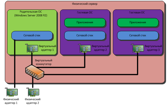
У нашего сервера имеется два сетевых интерфейса. Когда хостовая ОС только что была установлена, и интерфейсы сконфигурированы – к каждому из них привзяывается протокол TCP/IP, некоторые другие протоколы и соответственно – назначаются сетевые настройки (IP-адрес, маска подсети, адреса шлюзов и DNS) – статически или динамически, в данном случае – не суть важно.
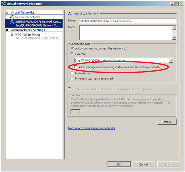
Виртуальные сети (то есть виртуальные коммутаторы) бывают трех типов: External, Internal и Private. External – виртуальная сеть, имеющая выход «во внешний мир». При создании сети типа External необходимо указать сетевой интерфейс, через который будет осуществляться выход наружу (Физический адаптер 2). При этом физический интерфейс теряет все сетевые настройки, и создается виртуальный адаптер в хостовой ОС (Виртуальный адаптер 1), к которому привязываются все необходимые протоколы и настройки. Физический же интерфейс остается всего с одним протоколом: Virtual Network Switching Protocol. Кроме этого, в Windows Server 2008 R2 появилась возможность создавать сети типа External, но при этом все равно изолировать их от хостовой ОС. Делается это снятием галочки «Allow management operating system to share this network adapter»:
ATTENTION: При создании виртуальной сети типа External происходит кратковременный разрыв сетевого соединения, и все настройки переносятся на новый, виртуальный адаптер. Об этом необходимо помнить во-первых, если настройка осуществляется удаленно – соединение может прерваться, и во-вторых – возможно придется заново настраивать Windows Firewall, чтобы привязать правила к новому виртуальному интерфейсу.
Internal – внутренняя виртуальная сеть, к которой могут подключаться только виртуальные интерфейсы – виртуальных машин и хостовой ОС. К физическому интерфейсу сеть типа Internal не привязывается, и, соответственно, выхода «вовне» не имеет.
Private – то же самое, что и Internal, за исключением того, что к такой сети могут подключаться только виртуальные машины. Сеть типа Private не имеет доступа ни ко «внешнему миру», ни к хостовой ОС.
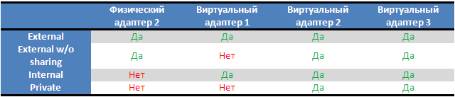
Для лучшего понимания – нарисую таблицу, в которой будет указано, какие интерфейсы будут подключены к виртуальному коммутатору, а какие – нет при разных настройках:
Работа с VLAN
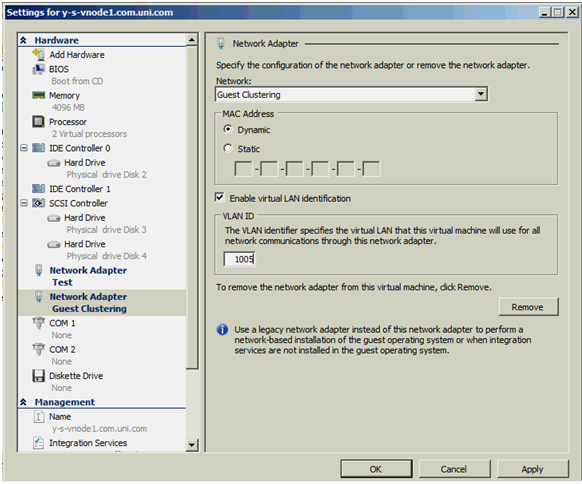
Hyper-V поддерживает работу с VLAN (IEEE 802.1Q). Для этого в свойствах виртуальных сетевых интерфейсов имеется галочка «Enable VLAN Identification», после активации которой можно ввести VLAN ID. Предварительно, разумеется, необходимо настроить коммутаторы, чтобы трафик тегировался соответствующими ID, и, разумеется, установить в хостовой ОС драйверы сетевого адаптера с поддержкой необходимых функций.
Более подробно о настройке виртуальных машин для работы с VLAN можно почитать в статье Дмитрия Макарова.
VMQ
Не могу закончить статью, не упомянув о новой фиче, появившейся в Windows Server 2008 R2 – поддержке виртуальных очередей, VMQ.
Поддержка VMQ позволяет перенести большую часть затрат на обработку сетевых пакетов, адресованных виртуальным машинам с хостовой ОС на плечи процессора сетевого адаптера. Разумеется, при условии, что сетевой адаптер это поддерживает, и в гостевых ОС установлены компоненты интеграции.
Если не используется VMQ, то обработка сетевых пакетов происходит следующим образом:
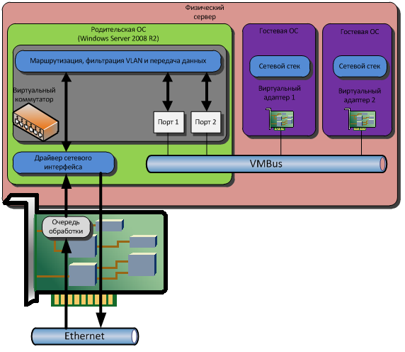
Распределением трафика по виртуальным машинам и фильтрацией по тегам VLAN при этом занимается виртуальный коммутатор, действующий в пространстве родительской ОС. При большом количестве виртуальных машин и при больших объемах трафика это может привести к некоторому снижению производительности, так как у процессора сервера есть и другие задачи, помимо обработки сетевых пакетов. Использование VMQ позволяет переложить обработку пакетов на плечи процессора сетевого адаптера:
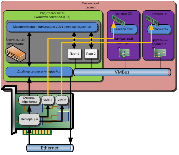
Сетевой адаптер, поддерживающий VMQ, способен самостоятельно осуществлять необходимую обработку сетевых пакетов, а затем записать данные непосредственно в область памяти соответствующей виртуальной машины.
Передача же данных, что с VMQ, что без оной – идет как и обычно: Виртуальный сетевой адаптер – VMBus – Виртуальный коммутатор – Физический сетевой адаптер.
Вместо заключения
На этом хотелось бы закончить статью, и заодно – рассказ об архитектуре Hyper-V. В заключение – хотелось бы спросить: у меня есть желание написать статью о Live Migration. Будет ли это интересно аудитории, или же все об этом слышали и все об этом знают?
In this article, we’ll show how to configure a tagged VLAN interface on Windows 10/11 and Windows Server 2019 (2022/2016/2012R2). The VLAN (Virtual LAN) specification is described in the IEEE 802.1Q standard and involves marking traffic with tags (vlanid) so that a network packet may be referred to a particular virtual network. VLANs are used to separate and segment networks, restrict broadcast domains, and isolate network segments to improve security. On Windows, you can configure multiple logical network interfaces with different VLAN ID on a single physical NIC using different tools.
Contents:
- Creating Multiple VLAN Interfaces on Windows 10 and 11
- How to Configure Multiple VLANs on Windows Server 2022/2019/2016?
- Create Multiple VLANs with Windows Hyper-V Role
In order to use VLAN on Windows, you need to reconfigure the physical switch port to which your computer/server is connected to. The port must be switched from access mode to trunk mode. By default, all VLANs are allowed on a trunk port, but you can set the list of allowed VLAN numbers (1 to 4094) available at this Ethernet switch port.
Creating Multiple VLAN Interfaces on Windows 10 and 11
Windows desktop editions don’t natively support VLAN tagging. By default, most network adapter drivers ignore all VLAN tags in network packets and external VLANs become inaccessible.
For some network adapters, you can set the VLAN number in the driver properties:
- Run the Device Manager (
devmgmt.msc); - Expand the Network adapters section and open the properties of your network adapter;
- Go to the Advanced tab and find the VLAN ID option;

- You can set the VLAN number here;
- For some NICs, you first need to enable the Packet Priority and VLAN option.

In modern versions of Windows 10 and 11, you can set one VLAN tag for a network interface adapter. You can use PowerShell to manage network settings. For example, you want to set VLAN ID 24 for your network interface named Ethernet0:
Set-NetAdapter –Name "Ethernet0" -VlanID 24
For some NICs (from Intel, Broadcom, HP, Realtek), special tools are available that allow you to create a virtual network interface in Windows with a VLAN ID. To do this, you need to install a special driver on your computer that supports 802.1Q tagged traffic and the official configuration tool from the vendor.
Create Multiple VLANs on a Realtek NIC in Windows 10 or 11
For Realtek NICs, you can configure multiple virtual NICs with different VLANs using the Realtek Ethernet Diagnostic Utility. Find the description of your Realtek network controller on the vendor’s website, and check that this model supports VLAN. For example, the specification for the RTL8169SC(L) network controller has this option:
Supports IEEE 802.1Q VLAN tagging
Download and install the latest network driver for your Realtek adapter and run the Realtek Ethernet Diagnostic Utility (Diagnostic Program for Win7/Win8/Win10/Win11).
Go to the VLAN section, click Add and add the required VLAN ID. After that, a new network interface will appear in Windows.
After creating network interfaces for your VLANs, you can assign the IP addresses from the corresponding IP network.
How to Setup VLAN on an Intel Ethernet Network Adapter?
Intel has its own Intel Advanced Network Services (Intel® ANS) tool for configuring VLAN interfaces. Your network adapter model, of course, must support VLAN (for example, VLAN is not supported for NICs such as Intel PRO/100 or PRO/1000). When installing the driver, select the Intel PROSet for Windows Device Manager and Advanced Network Services options.
Then a separate VLANs tab appears in the properties of your physical Intel network adapter, where you can create multiple VLAN interfaces.
However, this method works on all previous versions of Windows (up to Windows 10 1809). In modern Windows 10/11 builds, the following message is displayed in the VLANs tab:
Intel(R) Advanced Network (Intel(R) ANS) Teams and VLANs are not supported on Microsoft Windows 10.
Intel recently released new network adapter drivers and the Intel PROSet adapter configuration tool for the latest builds of Windows 10 and 11. Download and install the latest Intel driver and Intel PROset utility.
Run the configuration tool, go to the Teaming/VLANs tab, click the New button, and specify the name of the network interface and its VLANID.
In addition, you can add/remove/view the list of VLANs on Intel NICs using the PowerShell cmdlets from the IntelNetCmdlets module. Import the module into your PowerShell session:
Import-Module -Name "C:Program FilesIntelWired NetworkingIntelNetCmdletsIntelNetCmdlets" -Scope Local
You can create an untagged virtual network adapter (usually used with native-vlan-id):
Add-IntelNetVLAN -ParentName "Intel(R) Ethernet Connection I219-LM" -VLANID 0
To create an Intel NIC with a specific VLAN number:
Add-IntelNetVLAN -ParentName "Intel(R) Ethernet Connection I219-LM" -VLANID 103
To list all virtual Intel network adapters:
Get-NetAdapter
Remove VLAN interface:
Remove-IntelNetVLAN -ParentName "Intel(R) Ethernet Connection I219-LM" -VLANID 103

For Broadcom NICs, you can create groups of virtual network interfaces and assign VLAN IDs using the Broadcom Advanced Control Suite tool.
How to Configure Multiple VLANs on Windows Server 2022/2019/2016?
In Windows Server 2022/2019/2016/2012R2, you can configure multiple VLANs on the same network interface using built-in tools (without installing third-party drivers and tools). Let’s try to configure multiple VLANs on the same physical NIC in Windows Server 2019 using NIC Teaming.
Make sure that no VLAN number is set in the network adapter advanced settings (VLAN ID = 0). 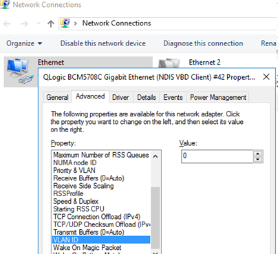
- Open the Server Manager -> Local and click the NIC Teaming link;
- In the Teams section, click Task -> New Team. Specify the group name and select network adapters to add;
You can create a NIC Teaming group using PowerShell:
New-NetLbfoTeam -Name vTeam -TeamMembers "Ethernet1","Ethernet2" -TeamingMode SwitchIndependent -LoadBalancingAlgorithm Dynamic - Then in the “Adapter and Interfaces” section, add virtual network interfaces. Click Tasks -> Add Interface;
- Enter the name of the interface you are going to create and a VLAN number;
You can add a network interface and set a VLAN for it in PowerShell:
Add-NetLbfoTeamNic -Team vTeam -VlanID 24 -Name VLAN24 - In the same way, you can add as many VLAN network interfaces as you need;
Please note that Windows Server 2022/2019/2016 supports a maximum of 32 NICs (and unique VLANs) per NIC Teaming group.
- A separate virtual network adapter will appear in the list of network connections in
ncpa.cpl;
- Now you can configure the IP settings for each VLAN interface in the properties of the network adapter or using PowerShell cmdlets:
New-NetIPAddress -InterfaceAlias your_VLAN_interface -IPAddress 192.168.10.10 -PrefixLength 24 -DefaultGateway 192.168.10.1

Set-DnsClientServerAddress -InterfaceAlias your_VLAN_interface -ServerAddresses 192.168.100.12
Create Multiple VLANs with Windows Hyper-V Role
You can programmatically handle multiple VLANs in Windows through the Hyper-V subsystem (available in both Windows Server and desktop Windows 10/11 Pro and Enterprise editions). You can create a virtual switch with a network adapter in a specific VLAN.
To do this, you need to install Hyper-V components:
Enable-WindowsOptionalFeature -Online -FeatureName:Microsoft-Hyper-V -All
Create a new virtual switch through Hyper-V Manager or using PowerShell commands (see an example in the article on how to configure Hyper-V Server).
Then run the following commands for each VLAN you want to create:
Add-VMNetworkAdapter -ManagementOS -Name VLAN24 -StaticMacAddress "11-11-AA-BB-CC-DD" -SwitchName vSwitch2

Set-VMNetworkAdapterVlan -ManagementOS -VMNetworkAdapterName VLAN24 -Access -VlanId 24
So a network adapter with the VLAN you want will appear in Windows.
If you have VMs running on your Hyper-V server, you can put them in different VLANs. To switch the virtual network adapter of a VM on Hyper-V to Access mode and allow it to receive traffic only with a specific VLAN ID, use the command:
Set-VMNetworkAdapterVlan -VMName MyVMName1 -Access -VlanId 30
Display a list of VMs and their assigned VLANs:
Get-VMNetworkAdapterVLAN
In Windows Server 2022 with the Hyper-V role, you won’t be able to bind a virtual switch to such a teaming interface. The fact is that LBFO NIC Teaming is a deprecated feature on Windows Server 2022 (https://aka.ms/lbfodeprecation). Instead of NIC Teaming, it is proposed to use Switch Embedded Teaming (SET).
Let’s create a virtual adapter and assign a VLAN to it on Windows Server 2022 Hyper-V using SET.
Create a virtual switch connected to the host’s physical adapters:
New-VMSwitch -Name HVVLANSwitch1 -NetAdapterName "Ethernet3","Ethernet4" -EnableEmbeddedTeaming $true
Now create a virtual adapter connected to the virtual switch:
Add-VMNetworkAdapter -ManagementOS -Name "VLAN22" -StaticMacAddress "XX-XX-XX-XX-XX-XX" -SwitchName HVVLANSwitch1
Assign a VLAN tag to your virtual adapter:
Set-VMNetworkAdapterVlan -ManagementOS -VMNetworkAdapterName "VLAN22" -Access -VlanId 22
You can enable the virtual Hyper-V adapter to receive packets from multiple VLANs using the command:
Get-VMNetworkAdapter -Name youradaptername | Set-VMNetworkAdapterVlan -Trunk -AllowedVlanIdList 40-69 -NativeVlanId 0
The -NativeVlanId 0 parameter is required. In this case, we tell Hyper-V that VLAN:0 is used as native for untagged traffic.
A How-To Guide on Setting Up Hyper-V VLANs
A virtual environment can consist of several physical servers, with multiple virtual machines (VMs) simultaneously running within each host. To ensure cooperation within such complex infrastructure, you need to enable communication between all of the system’s components. Previously, all communications between computers had been conducted using local area networks (LANs), which can span across only a limited area, or wide area networks (WANs), which can cover larger distances. Though effective, these types of networks can lack flexibility, scalability, and reliability.
However, achievements in server virtualization have triggered the development of network virtualization. As a result, virtual local area networks (VLANs) have been introduced, which can logically segment a physical LAN into different broadcast domains, thus allowing you to isolate network traffic in a secure and reliable way.
So, why should you deploy Hyper-V VLANs in the first place? – The answer is simple. A Hyper-V VLAN is a unique form of technology which can provide you with the following benefits:
- High performance. VLANs can decrease the latency and traffic load on the network and network devices.
- Using Hyper-V Manager or PowerShell cmdlets, you can easily create or delete virtual network adapters as well as virtual switches, thus allowing you to increase or decrease the scale of your virtual networks on demand.
- Using VLAN tags, you can easily isolate network traffic as well as restrict access to confidential information.
- VLANs can easily add, move, or change hosts on the network.
- With VLANs, you can access network services from any physical location, and an IT administrator can control the network traffic from a single pane of glass.
- Cost-efficiency. If your organization has multiple departments operating in various geographical locations, network virtualization eliminates the need for deploying expensive LANs for each geographical area.
In today’s blog post, we shall discuss in detail what a Hyper-V VLAN is, how virtual networks work, and which steps should be taken to deploy a Hyper-V VLAN in your infrastructure. Also, read further to learn what NAKIVO Backup & Replication can offer to protect your virtual environment.
What Is a Hyper-V VLAN?
A virtual LAN (VLAN) is a group of computers, servers, and other network devices which are logically connected and appear to work as a single LAN, regardless of their physical location. Previously, we had to create separate networks (for example, LAN 1 and LAN 2), with each of them operating in the same geographical area and having an individual switch. Due to the fact that LAN 1 and LAN 2 are two separate physical networks, the host connected to LAN 1 could not communicate with the host connected to LAN 2 and vice versa as there was no physical connection between their switches.
So, how do networks actually work? For example, you have two different departments, and don’t want these departments to have access to one another’s traffic. Hence, we would need to separate those networks. It can be done either physically (through creating individual LANs for each department) or digitally (through creating several VLANs). In a nutshell, creating and deploying two physical LANs is the same as deploying two virtual LANs. The difference is that two physical LANs or more would require separate switches, whereas two virtual LANs or more can operate on a single switch.
Hyper-V VLAN technology enables logical segmentation of networks, meaning that you can take a single switch and divide it into multiple logical networks. Note that the traffic of each network runs in isolation. Therefore, even though all virtual networks share the same hardware, Hyper-V VLANs can identify and read only their own network traffic. In truth, each virtual network is unaware of other virtual networks and is disconnected from them.
Moreover, by creating multiple Hyper-V VLANs, you can improve security within your system. For example, if you create different virtual networks for various departments and assign each department employee to a corresponding network, you can ensure that only selected users are granted access to confidential information.
Data Protection with NAKIVO Backup & Replication
NAKIVO Backup & Replication delivers high-end data protection for SMBs and enterprises with multiple backup, replication and recovery features, including VMware Backup, Hyper-V Backup, Office 365 Backup and more. Get the Free Trial now!
Requirements for Hyper-V VLANs
In order to create and deploy Hyper-V VLANs, you would need to follow these requirements:
- Ensure that all networking hardware, including switches, routers, and network adapters, support the 802.1q standard, which helps to assign a tag into each Ethernet frame.
- Devices connected to the same VLAN must be assigned the same VLAN ID so as to enable secure communications between them. The VLAN identifier specifies the virtual LAN that this VM can use for conducting network communications through this network adapter.
- The host must run Windows Server 2008 (or later) or Hyper-V Server.
How to Set Up a Hyper-V VLAN
Generally, the process of setting up a Hyper-V VLAN requires two steps. First, you need to configure the virtual switch to enable network traffic on the physical switch port. Second, you must configure the VM to use a unique VLAN identifier for future network communications.
Configuring the Hyper-V virtual switch
In order to configure a selected virtual switch, you should do the following:
1. Open Hyper-V Manager.
2. In the Actions pane, click Virtual Switch Manager.

Here, you can create a new virtual switch (external, internal, or private) or you can configure the existing switches.
3. After selecting the required switch, you get access to configuring the virtual switch properties. In the VLAN ID section, check the Enable virtual LAN identification for management operating system Also, you must assign a unique VLAN identifier which will be used for network communications.

4. Click OK to save changes.
Configuring the Hyper-V virtual machine
The next step is to configure the VM to use VLAN identification. For this purpose, you need to take the following steps:
1. Open Hyper-V Manager.
2. In the Virtual Machines section, right-click the VM you would like to configure and select Settings.

3. Click Network Adapter to see network adapter properties. Check that the network adapter is connected to the right virtual switch.

4. Next, check the Enable virtual LAN identification box and assign the same VLAN ID that you used earlier. As a result, all network traffic travelling through the physical network adapter connected to this virtual switch will be tagged with the VLAN ID you have just set.

5. Click OK to save changes.
Your VM and a virtual switch have been properly configured and you can now ensure reliable traffic isolation using Hyper-V VLANs.
Once you have built a Hyper-V environment and made sure that it works as required, you need to take care of its security. NAKIVO Backup & Replication is a reliable, affordable, and powerful data protection solution, which can help you protect multiple environments using the following data protection options: backup, backup copy, backup to cloud, replication, and site recovery.

In the first part of this series, we started with the foundational concepts of networking in the OSI model and took a brief look at where Hyper-V components live in that model. In this part, we’ll build on that knowledge by looking at the operation of VLANs and how they work within the context of a Hyper-V deployment.
- Part 1 – Mapping the OSI Model
- Part 2 – VLANs
- Part 3 – IP Routing
- Part 4 – Link Aggregation and Teaming
- Part 5 – DNS
- Part 6 – Ports, Sockets, and Applications
- Part 7 – Bindings
- Part 8 – Load-Balancing Algorithms
Last updated: November 15, 2015.
“VLAN” is an acronym for Virtual Local Area Network. This concept predates most of the virtualization technologies that are common today and should not be confused with anything in the computer virtualization or software-defined networking worlds.
To recap the first post, the VLAN exists at layer 2 in the OSI model. The significance is that this has nothing to do with IP addresses, although some of the basic rules are similar. Everything at this level is done by MAC address. Within any given Ethernet network, all endpoints must have a MAC address and all MAC addresses must be unique. Usually that’s not tough, given that any single prefix can have almost 17 million unique MAC addresses and manufacturers with that many devices also have more than one prefix.
What a VLAN does is set up a unique Ethernet network. The definition that I commonly see is that each VLAN represents a distinct “broadcast network”. While this explanation is the simplest, I dislike it as it is often confused with IP broadcasting. In Ethernet networking, a “broadcast network” indicates all the endpoints that will receive a frame transmitted to FF-FF-FF-FF-FF-FF. Even though it’s not a wonderful definition, most of the others get so complicated that you forget the question. So, rather than dig into it like that, just look at the functionality.
In a simple network using very basic switches, that means every single endpoint that is plugged-in and live will receive a broadcast. Switches capable of setting up VLANs can specify that some of their switch ports are members of a particular VLAN. So, an Ethernet frame traveling on VLAN 1 will not be delivered to any switchport that is not a member of VLAN 1. However, this distinction is entirely “virtual”. The only thing that sets the frames apart is the value in the 802.1q tag — and it might not even be there.
Most network devices can’t process an 802.1q tag at all. If an Ethernet frame is received with one, they will treat the frame as malformed and ignore it. For this reason, you rarely want to point frames with 802.1q tags at physical devices other than switches. Usually, the tag is only present is when a frame passes through a “trunk”. A trunk is a single connection that carries multiple VLANs. In all other cases, switches keep track of which VLAN that traffic for a given port should be in.
Access Mode/PVID
In Cisco and Microsoft networking, ports can be set in “access mode”. If they aren’t set with anything else, then they will always communicate using untagged frames. In the Cisco world, this could be subjected to the device’s default VLAN. The Hyper-V switch has no default VLAN, or perhaps more properly, the default is always untagged. If the port is set to a specific VLAN, then that port becomes a member of that VLAN. Its frames are still untagged, but the switch will only allow that port to communicate with other devices on the same VLAN. The non-Microsoft/non-Cisco world corollary to an access mode port is PVID (port VLAN identifier). Only the term is different. Functionality is the same. To reiterate, access mode ports move traffic untagged, but only within a single specified VLAN.
Trunk Mode/Tagged
In Cisco and Microsoft networking, ports can be set in “trunk mode” instead of access mode. The purpose of trunk mode is to connect to another switch. In trunk mode, the port can become a member of multiple VLANs. VLANs that the trunk should process are added to the allowed list for Cisco and Microsoft switches. On most other devices, a port is considered to be in the equivalent of trunk mode by virtue of having one or more VLANs specified in its “tagged” list. Frames with other tags are discarded.
Native/Untagged VLANs
A trunk on a Cisco or Microsoft switch can be assigned a native VLAN. It then becomes a member of the network shared by all ports on the switch assigned to that VLAN just as it would if that were simply another of the allowed VLANs. Only one VLAN can be configured on a trunk in this method, or traffic in these VLANs would be inextricably combined into a single network. This is because frames that this trunk sends to the other switch travel without an 802.1q tag, and all incoming frames without a tag are treated as members of this VLAN. For a Cisco/Microsoft switch, this will be determined by the receiving trunk’s native VLAN setting. For all others, the equivalent fo the native VLAN is set by designating a single untagged VLAN for the trunk.
Comparing Cisco/Microsoft to other Manufacturers
The nice thing about the Cisco/Microsoft switches is that the usage of “access mode” and “trunk mode” make it pretty clear what’s going on. For everyone else, use “PVID” instead of “access mode” and “tagged” and/or “untagged” instead of “trunk mode”.
Clarifying the Frames
Now that the terminology has been explained, we’ll return to the frames themselves. When it comes right down to it, there is only one functional difference between the operation of an access-mode port and a trunk-mode port, and that is the presence, or lack thereof, of the 802.1q tag. Packets that move across access ports should never have these tags. If they have them, the switch will get rid of them; to not to do would be a quick path to enabling a break-out attack. Packets that move across trunk ports will always have these tags.
Access frame (untagged) diagram:

Access Mode Packet
Trunk frame (tagged) diagram:

Tagged Packet
It’s not entirely clear from the diagrams, because I didn’t want them to be too complex, but there’s only a single segment that gives any indication of how much data is in the packet. That’s in the portion that I marked as “length/type”. Notice where in the sequence that it sits. Since the preceding portions don’t have any indication of what’s coming, the device receiving the packet has to make assumptions. Therefore, a switch will assume everything coming in on a trunk port has an 802.1q tag and every packet coming in on an access mode port does not have an 802.1q tag. All other devices don’t even know that’s there’s any other type of frame than the one shown in the first image. So, if they receive a tagged frame, they believe that they’re parsing the length or type portion of the packet, but they’re actually looking at the 802.1q tag. To them, the packet looks malformed.
This is the reason that VLANs are numbered from 1-4096. You can, of course, have an all-zero tag, but there is no VLAN 0. The so-called “untagged” frame can’t cross a trunk port without the 802.1q tag being present. It just goes (or arrives) with all zeroes. But, as the above headings indicate, the “untagged” frame is not on access ports in the same way. The switch handles port membership. Packets always travel on those ports without even the space for an 802.1q tag.
As for the Hyper-V switch, this is one reason why it doesn’t have a “default VLAN”. It doesn’t really need one. If you don’t designate a VLAN for any given virtual network adapter, then it will be in the “default VLAN”. Packets coming in to the Hyper-V switch with an empty tag can be delivered to those adapters. Packets coming out of them meant for the external world will be sent out with an empty 802.1q tag and the receiving switch will place them into whatever VLAN it has set as untagged or native for its trunk. I suspect another reason that the Hyper-V virtual switch doesn’t use a numbered default VLAN might be related to the fact that it also needs to be able to connect to switches that can’t handle 802.1q tags. When configuring a hardware smart switch to talk to such a simple switch, you’d just leave its port in access mode. Hyper-V’s uplink doesn’t grant the distinction.
Hypothetical VLAN Configuration
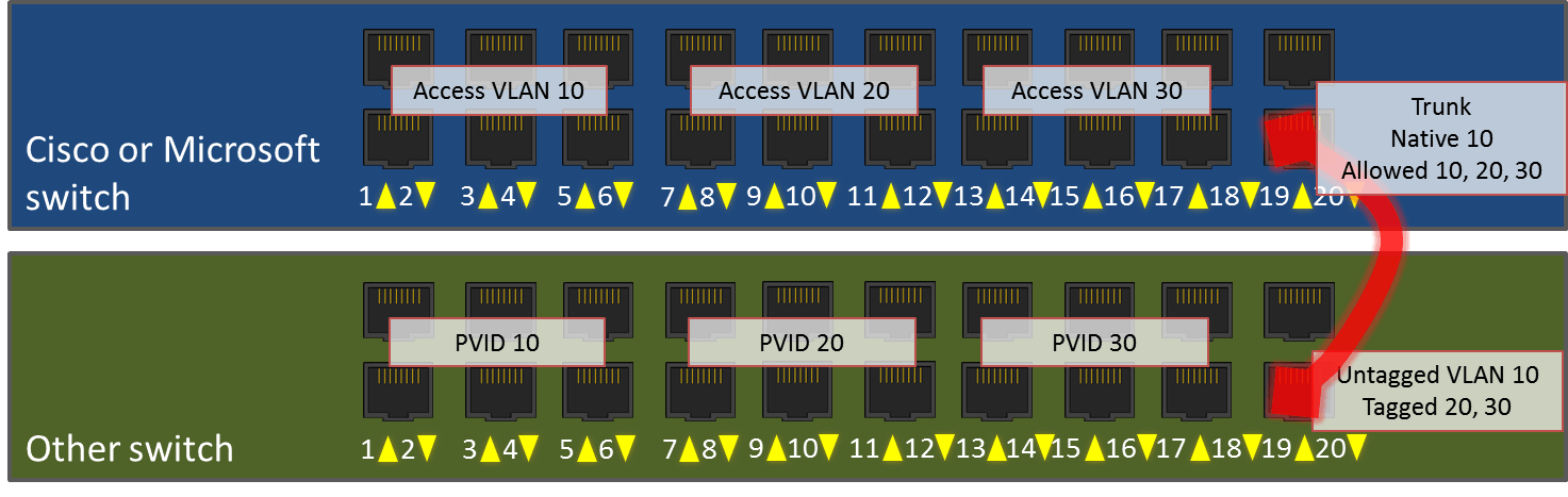
Let’s look at an example deployment that uses all of these concepts. I have one Cisco 20-port smart switch (or a Microsoft Hyper-V external virtual switch) and one Netgear 20-port smart switch. I’m going to configure them as identically as possible, then plug them into each other.
In my network, I’ve decided that servers should participate in VLAN 10, desktops should participate in VLAN 20, and printers should participate in VLAN 30. On each switch, I want to designate ports 1-6 for servers, 7-12 for desktops, 13-18 for printers, and 20 for the link between switches. I will leave 19 unused.
Access Port Configurations
On the Cisco switch, I will set ports 1-6 in access mode for VLAN 10. I will set ports 7-12 in access mode for VLAN 20. I will set ports 13-18 in access mode for VLAN 30. I will plug in the devices as normal and just give them IP addresses as normal.
On the Netgear switch, I will assign ports 1-6 a PVID of 10. I will assign ports 7-12 a PVID of 20. I will assign ports 13-18 a PVID of 30.
Trunk Port Configurations
On the Cisco switch, I will set port 20 to trunk mode. I will give it a native VLAN of 10 and add 10, 20, and 30 to its allowed VLANs list.
On the Netgear switch, I will set port 20 so that it allows untagged traffic for VLAN 10 and tagged traffic for VLANs 20 and 30. As a matter of habit, I also usually set these with a PVID that matches the untagged VLAN, but I don’t think that’s actually necessary.
So that there’s no confusion on default VLAN vs. untagged/native VLAN, most standard smart switches only allow VLAN 1 to be the default VLAN for access mode ports. There is no coupling between a trunk port’s untagged/native VLAN and any of the access ports. In case this isn’t clear, remember that a single switch can have multiple trunk ports with their own untagged/native VLANs. This behavior is different from the Hyper-V virtual switch, which simply does not number its “default” VLAN.
Results
Now that this is done, I’ll plug in servers, desktops, and printers to all these ports as indicated. I will use a standard patch cable to connect port 20 on the Cisco switch to port 20 on the Netgear. Now, the server plugged into port 1 on the Cisco switch will be able to send and receive Ethernet frames directly to/from devices plugged into ports 2-6 and 20 on the Cisco switch and ports 1-6 and 20 on the Netgear switch. Those frames will never be tagged.
A desktop plugged into port 7 on the Cisco switch will be able to send and receive Ethernet frames directly to from devices in ports 8-12 on that switch and 7-12 on the other. However, unlike the VLAN 10 ports, its frames will cross the inter-switch link with an 802.1q tag of 20. Once these tagged frames arrive on the receiving switch, the tag is removed. But, the switch will still only allow those frames to be visible to ports that are members of VLAN 20 (ports 7-12). So, while a packet moves between ports on the same switch, the switch knows which port members to expose it to by port VLAN membership. When a packet is sent between switches, the sending switch will place an 802.1q tag it so that the receiving switch knows which of its ports it can be exposed to. Once the receiving switch knows what that packet’s tag is, it will remove the tag.
Port Channels/Link Aggregation
 Port Channels/Link Aggregation
I know that at least a few of you are looking at that diagram and wondering why I wouldn’t put ports 19 and 20 on both switches into an aggregated link. The answer is: actually, I would. That’s not what this article is about though. We’ll revisit all that in a later installment.
Management VLANs
I haven’t talked about management VLANs, which is mostly because they’re not really in-scope for Hyper-V. Hyper-V either tags a frame or it doesn’t; it doesn’t really have a concept of a default VLAN or a management VLAN.
The management VLAN is really just a VLAN that compliant network devices will respond on. So, if I assign an IP of 192.168.75.100 to a switch, it will give that IP address a presence inside its designated management VLAN’s Ethernet space. The default for most devices is VLAN 1, and for security purposes, it’s usually recommended that you change it. Since the Hyper-V switch has no IP address, it has no purpose for a management VLAN. The management VLANs are trunked and (un)tagged and accessed and PVID’d just like any other VLAN, although also for security purposes, it’s best if only network infrastructure devices’ management IPs are in it.
Hyper-V VLANs
The Hyper-V terminology usually lines up better with Cisco than with the others (confusing or not, these others are actually following standards most closely). The first difference is that you never really see anything about virtual switch ports unless you travel deep down the path where most are afraid to tread. Usually, you set these options directly on the virtual network adapter. That’s works well in this case because Hyper-V controls the switch, the switch ports, and the virtual network adapters. So, it doesn’t really need to distinguish between the port and the adapter.
When the Hyper-V virtual switch takes over a physical network adapter, that network adapter become an “uplink”. So, instead of the Cisco switch in our example network above, imagine that it’s a Hyper-V switch. The host’s physical adapter it’s assigned to is plugged into port 20 on the Netgear.
The big thing to be aware of is that we don’t, and can’t, configure this particular trunk “port” in Hyper-V. So, no native/untagged VLAN when connecting in to the physical network. This just means that Hyper-V isn’t going to be able to strip VLAN ID’s from traffic leaving virtual machines. It will be able to accept incoming untagged traffic, of course. Just leave the VLAN ID off of any virtual adapter you want to receive from the incoming switch’s native VLAN ID. The Hyper-V switch’s “uplink” port will send the outgoing traffic of any VM without a defined VLAN without an 802.1q tag, so it will end up in the connected switch’s native VLAN.
Besides that, the Hyper-V virtual switch behaves like any other switch. Switch ports are set in access mode. As previously stated, any port without a defined VLAN winds up in the connected switch’s native or untagged VLAN. All other ports communicate on their designated VLAN, which is analogous to Cisco’s access mode or a non-Cisco switch’s PVID.
VLAN Isolation
By their very nature, VLANs are isolated. You can’t move traffic from one VLAN to another without communicating through a device that is present on both VLANs. There is a capacity issue, however, as there is a maximum of 4095 VLANs. There is a functionality issue if you need to connect duplicate IP subnets to the same router. While exceedingly rare in the SMB space, these situations are not uncommon at companies that host networks for others. As an example, you might have two clients who both use 192.168.0.0/24. The easiest way to deal with that is to simply use a dedicated VLAN for each client and ensure that they can only communicate off of their own VLANs by using a router that employs network address translation (NAT). But, this is still subject to the scalability issue.
The first option is to use Private VLANs. This requires nothing other than what Hyper-V itself can provide. With this configuration, each virtual adapter to use a private VLAN has three configuration steps. First, it is set as promiscuous, community or isolated. Second, it is given a primary VLAN. Finally, depending on the mode, it is given a secondary VLAN or a list of allowed secondary VLANs. How it behaves depends on the first option that was set. This isn’t something I want to spend a lot of time on, first because I’m not very well-versed in it myself and second, I expect that if you really need it, you have access to a network engineer who can explain it to you and/or help you configure it.
The second option is to use network virtualization. This requires VMM, but it also allows you to create fully isolated networks. I also won’t spend much time on this, partially because I feel it’s been done better elsewhere, partially because I’m also not well-versed in it, and partially because, just like private VLANs, I don’t see where the majority of installations will have an immediate need for it. But, because I think that the hybrid cloud will eventually encroach on most of our networks. I do think this is something that’s worthwhile for most Hyper-V administrators to learn in the long run. Just not necessarily right away.
Hyper-V Switch Trunk Mode
The Hyper-V switch allows you to set a virtual adapter into trunk mode. The usefulness of this is in the eye of the beholder, since unlike a physical switch, a Hyper-V switch can only provide a connection between virtual machines and a single physical switch. So, aside from the trunk that exists on an external virtual switch represented by the physical NIC, it can’t trunk to any other switch. Also, as you’ll remember from the first post in this series, VLANs exist at layer 2. IP addresses don’t appear until layer 3. The practical meaning of that is that all the things you’re used to configuring inside virtual machines know nothing about VLANs. The frames will arrive with the 802.1q tag intact, but you’ll need an application inside the guest that knows what to do with it in order to make any use of this feature. What I see people trying to do is set up the Windows Remote Access Service (RAS, formerly Routing and Remote Access Service, or RRAS) to process VLANs. RAS works at layer 3 and above, so it can’t process these VLAN tags.
Next Steps
As a natural segue, the next thing we’re going to do is step up from layer 2 to layer 3 and look at IP addressing and routing within the context of Hyper-V.
Comments
-
4 Jan 2014 9:01 PM
HyperV with VLANID does not work!
Hello,
I created a nic teaming with 3 network cards and a virtual switch.
My need is to create the following scenario:
— Nic Teaming with 3 network cards
— VEthernet (Live migratory-on) — 1 VLANID
— VEthernet (ClusterHB) — VLANID 2
— VEthernet (Management Backup) — VLANID3
I have two switches cascaded in (LinkAgredation / Trun-k).
My server is connected as follows: NIC1: SW1, NIC2: SW2, CIN3: SW1
I asked for support networks configure the switch ports which I will use for my NICs in Trunk.
Here we go:
— I created the Nic Teaming in Independent mode — HyperV-Port
— Created vEthernet (Live migratory-on) — 1 VLANID
— Created vEthernet (ClusterHB) — VLANID 2
— Created vEthernet (Management Backup) — VLANID3
My main network I’m connected is in VLANID 3 (172.16.16.50) and try to ping the vEthernet (Managment B-ackup) — VLANID3 that has the IP: 172.16.16.60 does not work.
I removed the NIC Teaming and put the IP: 172.16.16.60 on each (NIC1, NIC2, CIN3) to verify if there was any problem in the SW configuration, but the ping worked normally.
The problem only occurs after creating the nic teaming.
PS1: I put the IP: 172.16.16.60 directly in the Nic Teaming driver, I type changes Nic Teaming for static and not funciounou too.
PS2: I created a second nic teaming, as your blog and assigns putting VLANID3 and neither worked an IP.
What am I doing wrong?
Thank you….
-
1 Aug 2014 12:04 PM
Verify that your swithports are configured for LACP (802.3AD).
Verify that the trunked port is configured to forward VLAN1, VLAN2, VLAN3 (in your case).
Verify that your nic teaming is bonded and using LACP
-
8 Apr 2015 1:02 PM
Sandro,
You probably made a common mistake. You should not use VLAN tagging on a NIC Team (tNICs) and the vSwitch at the same time. Because once you tag VLAN 3 for vManagement on the tNIC, VLAN is not forwarded anymore to your vSwitch. This is also an unsupported scenario.
If you need multiple vNICs for the parent OS and also a vSwitch on the same team. Create the vNIC on top of the vSwitch with tagging. This is described in chapter from the following document…
Windows Server 2012 R2 NIC Teaming (LBFO) Deployment Guide
download.microsoft.com/…/Windows%20Server%202012%20R2%20NIC%20Teaming%20(LBFO)%20Deployment%20and%20Management.docx
Процесс перехода от традиционной инфраструктуры к виртуальной может оказаться физически (да и психологически) сложной задачей для администратора, поскольку терминология и возможности систем виртуализации иногда отличаются от изученного ранее. Для тех из вас, кто изучает различные аспекты виртуализации и системы Hyper-V, мы продолжим публиковать полезные статьи, подробно рассматривающие многочисленные возможности системы Hyper-V.
Сегодня я хочу рассказать о виртуальном коммутаторе Hyper-V (vSwitch) в Windows Server 2012 R2. Но сперва уделите немного времени чтению следующих вопросов:
- Что такое виртуальный коммутатор Hyper-V vSwitch?
- Какие типы коммутаторов vSwitch существуют в системе Hyper-V и в чем их различия?
- Что представляет собой команда PowerShell для удаленной настройки vSwitch?
- Как я могу настроить ВМ (виртуальную машину) на обнаружение только внутренней сети, но не интернета?
Какой-нибудь из этих вопросов кажется вам знакомым? Если да, прочитайте эту статью до конца. У меня есть ответы!
Hyper-V vSwitch — это программно-определяемый коммутатор трафика сети Ethernet, работающий на канальном уровне (layer-2). С его помощью сетевые администраторы могут подключать ВМ как к физическим, так и к виртуальным сетям. Он доступен по умолчанию при установке Hyper-V Manager и содержит улучшенные средства обеспечения безопасности и отслеживания системных ресурсов. Как и в случае других возможностей среды Hyper-V, в состав каждой новой версии Hyper-V входит улучшенная версия vSwitch. В настоящее время коммутатор vSwitch считается очень надежным, но в него продолжают вносить улучшения. Например, в среде Hyper-V 4.0 (той, что в Windows 2012 R2) предусмотрено множество возможностей для внутреннего изолирования и защиты сети от вредоносных ВМ.
Поскольку я не вижу смысла в теории без практики, хотелось бы перейти в Hyper-V Manager и позволить вам самим увидеть и оценить все возможности.
Установка Hyper-V vSwitch
В ходе установки среды Hyper-V предварительная настройка V vSwitch не выполняется. Если вы попытаетесь создать ВМ сразу после процесса установки, подключиться к сети вам не удастся. Чтобы настроить сетевую среду, выберите Virtual Switch Manager (Менеджер виртуального коммутатора) на правой панели приложения Hyper-V Manager.
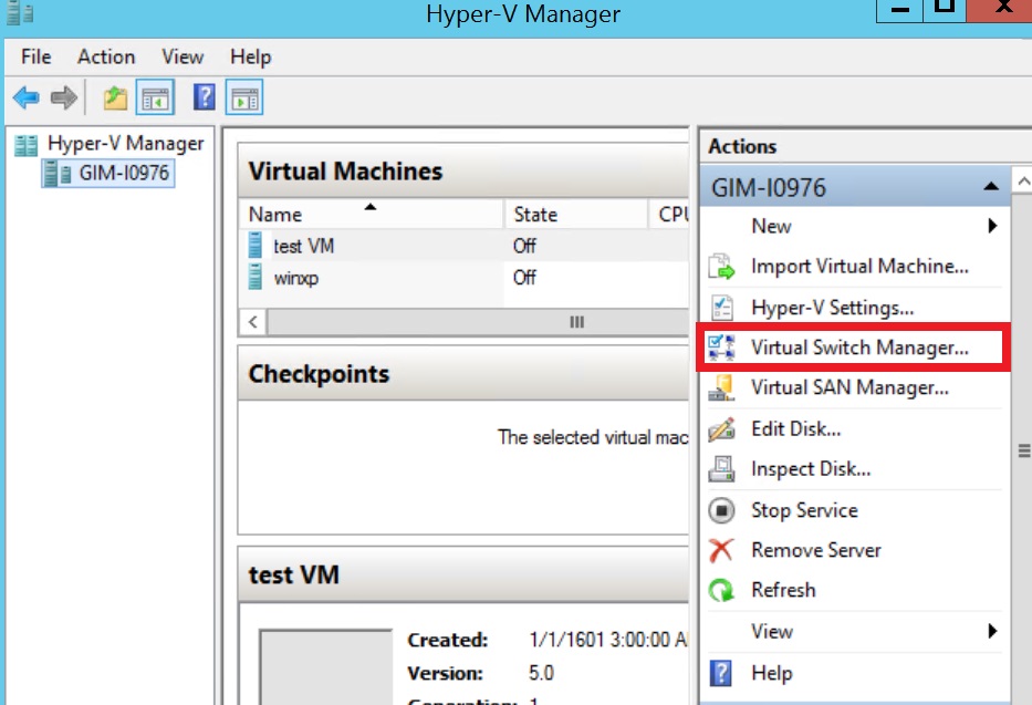
Рис. 1. Hyper-V Manager
Virtual Switch Manager упрощает настройку параметров коммутатора vSwitch и глобальной сети, что дает возможность изменять пространство стандартных MAC-адресов (примечание: изменение пространства MAC не будет влиять на существующий виртуальный коммутатор).
Создание виртуального коммутатора простая процедура. Для создания доступно три типа коммутаторов vSwitch:
- Внешний vSwitchсоединит физический сетевой адаптер хоста Hyper-V с виртуальным и затем предоставит вашим ВМ доступ за пределы хоста — в вашу физическую сеть и интернет (если физическая сеть подключена к интернету).
- Внутренний vSwitchследует использовать для построения независимой виртуальной сети, в которой подключенные ВМ будут «видеть» друг друга, а также хост гипервизора.
- Частный vSwitchсоздаст виртуальную сеть, в которой все входящие в соединение ВМ будут «видеть» друг друга, но не хост Hyper-V. В этой тестовой среде ВМ будут полностью изолированы.
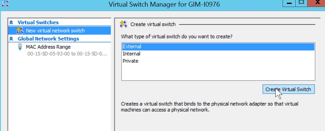
Рис.2 vSwitch Manager
Создание внешнего коммутатора vSwitch
Мастер создания предлагает вам выбор нескольких настроек при создании внешнего vSwitch.
- Можно выбрать нужный физический сетевой адаптер, если подходящих vSwitch у вас несколько.
- Опция Allow management OS to share this network adapter(Разрешить управляющей операционной системе создавать общий доступ к этому сетевому адаптеру) по умолчанию включена. Отключение этой опции лишит ОС гипервизора возможности сетевого подключения. Будьте осторожнее при создании vSwitch удаленно. Это может полностью разорвать соединение с удаленным хостом.
- SR-IOV(Single Root I/O Virtualization) (Виртуализация ввода-вывода с единым корнем) позволяет подготовить такую конфигурацию, которая может увеличить пропускную способность сети путем перенаправления трафика напрямую в ВМ в обход коммутатора vSwitch. Информация о включении опции SR-IOV доступна здесь. Необходимо учесть несколько аппаратных и системных требований: совместимость BIOS, поддержка SLAT процессором и сетевой картой SR-IOV PCIe в вашей системе. Убедитесь заранее, что вы знаете, что делаете.
ПРИМЕЧАНИЕ: Вы не сможете включить опцию SR-IOV для существующего коммутатора vSwitch. - VLAN ID: Эта настройка разрешает создание виртуальной локальной сети (VLAN) в управляющей ОС. Верно это и для физической среды, настройка позволяет выделить трафик гипервизора путем предоставления отдельных широковещательных доменов внутри единой сети.

Рис. 3. Создание внешнего коммутатора vSwitch
Нажав кнопку Apply (Применить), будьте готовы потерять возможность физического сетевого подключения на время, пока среда Hyper-V выключит физический сетевой адаптер, настроит коммутатор vSwitch и заново их включит:

Рис. 4. Предупреждение при создании внешнего vSwitch
Процедура создания внутреннего и частного коммутатора vSwitch аналогична, хотя некоторые настройки, такие как общий доступ к сети и SR-IOV будут недоступны и выделены серым цветом, что связано с самим характером этих коммутаторов.

Рис. 5. Создание внутреннего коммутатора vSwitch
ПРИМЕЧАНИЕ: Возможна автоматизация процедуры с помощью скрипта PowerShell, как и в случае других административных операций Windows 2012 R2. Полный синтаксис скрипта нуждается в проверке на сайте TechNet, но несколько примеров скриптов PS приведено ниже.
ПОДСКАЗКА: Не забудьте запустить консоль PowerShell с повышенными правами.
Следующая команда создает внешний коммутатор vSwitch для сетевого адаптера “Ethernet”:
New-VMSwitch -Name "External vSwitch" -NetAdapterName "Ethernet" -AllowManagementOS 1 -Notes "PowerShell example of External vSwitch creation"
Следующая команда создает внутренний коммутатор vSwitch:
New-VMSwitch -Name "Internal vSwitch" -SwitchType "Internal" -Notes "PowerShell example of Internal vSwitch creation"
Тип коммутатора vSwitch определяется параметром “-SwitchType «Internal/Private» или в случае внешнего vSwitch одним из следующих параметров: “-NetAdapterName «имя физического сетевого адаптера» / -NetAdapterInterfaceDescription «описание физического сетевого адаптера»”.

Создав коммутаторы vSwitch, вы можете их использовать в настройках сетевого подключения ваших ВМ.

Рис. 6. Мастер создания новой ВМ
ПОДСКАЗКА: Проверьте, к какому из всех vSwitch подключены ваши ВМ, с помощью команды:
Get-VMNetworkAdapter -VMName *
Подключение к сети ВМ
Имейте в виду, что подключенные к внутреннему или к частному коммутатору vSwitch виртуальные машины получат IP-адрес автоматически только в случае, если в той же виртуальной сети присутствует DHCP-сервер. Если DHCP-сервер отсутствует, выполните небольшую пост-конфигурацию ВМ, подключенных к частному vSwitch:
1. Перейдите в панель управления Network Connections (Сетевые подключения) ОС гипервизора и найдите подключение, относящееся к внутреннему vSwitch. Настройте статический IP-адрес и маску подсети вручную:

Рис. 7. Пост-конфигурация внутреннего коммутатора
2. Включите ВМ и задайте сетевому адаптеру ВМ нужный статический IP-адрес той же подсети, чтобы установить сетевое подключение. Задав правильные настройки, вы сможете проверить с помощью ping-запроса гипервизору, все ли настроено верно.

Рис. 8. Проверка возможности сетевого подключения внутреннего коммутатора
Для настройки частного коммутатора vSwitch используйте статические IP-адреса для всех ВМ и разместите их в одной подсети.
Вот и все! Позже я опубликую еще несколько полезных материалов о среде Hyper-V. А пока поделитесь со мной своим опытом виртуальной сетевой коммутации в среде Hyper-V. Какие-либо сложности, подсказки или комментарии? Все то, чем вы хотели бы поделиться.