В этой статье мы покажем, как настроить тегированный сетевой интерфейс с VLAN в Windows 10/11 и Windows Server 2019 (2022/2016/2012R2). Стандарт VLAN (Virtual LAN) описан в 802.1Q и предполагает маркировку трафика с помощью тегов (vlanid), необходимую для отнесения сетевого пакета к той или иной виртуальной сети. VLAN используются для разделения и сегментирования сетей, ограничения широковещательных доменов и изоляции сегментов сети для повышения безопасности. В Windows вы можете настроить несколько логических сетевых интерфейсов с разными номерами VLAN на одном физическом интерфейсе несколькими способами.
Содержание:
- Настройка VLAN интерфейсов в Windows 10 и 11
- Добавить несколько VLAN ID в Windows Server 2019/2016
- Как создать несколько VLAN в Windows Hyper-V?
Для использования VLAN необходимо соответствующим образом перенастроить порт коммутатора, куда подключен ваш компьютер/сервер. Порт должен быть переведен из режима access в режим транк. По умолчанию на транк порту разрешены все VLAN, но вы можете указать список номеров разрешенных VLAN(от 1до 4094), которые доступны на данном порту коммутатора Ethernet.
Настройка VLAN интерфейсов в Windows 10 и 11
В десктопных версиях Windows нет встроенный поддержки VLAN. По умолчанию драйвера большинства сетевых адаптеров обрезают в пакетах все VLAN-тэги и внешние VLAN становиться недоступными.
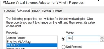
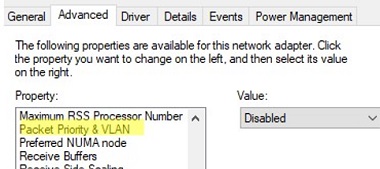
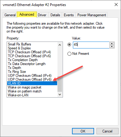
Для некоторых сетевых адаптеров вы можете задать номер VLAN в настройках драйвера:
- Запустите консоль диспетчера устройств (
devmgmt.msc
); - Разверните секцию Network adapters и откройте свойства вашего сетевого адаптера;
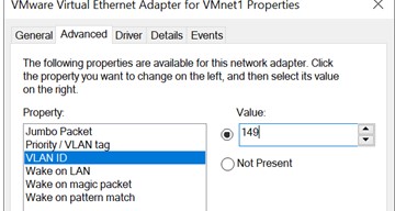
- Перейдите на вкладку Advanced и найдите опцию VLAN ID;

- Здесь вы можете задать номер VLAN;
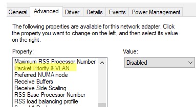
- У некоторых сетевых карт сначала нужно включить опцию Packet Priority and VLAN.

В современных версиях Windows 10 и 11 вы можете задать один тег VLAN для вашего сетевого интерфейса. Для этого используется командлет PowerShell для управления сетевыми настройками. Например, вы хотите задать VLAN 50 для вашего сетевого интерфейса с именем Ethernet1:
Set-NetAdapter –Name "Ethernet1" -VlanID 50
Для некоторых сетевых карт (Intel, Broadcom, HP, Realtek) доступны специальные утилиты, позволяющие создать в Windows виртуальный сетевой интерфейс с VLAN ID. Для этого на компьютере нужно установить специальный драйвер с поддержкой тегированного трафика 802.1Q и официальную утилиту от вендора.
Создаем VLAN интерфейсы в Windows 10/11 на сетевой карте Realtek
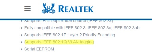
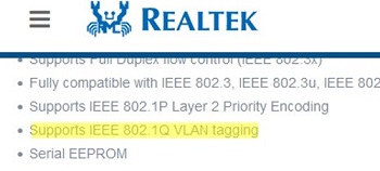
Для сетевых карт Realtek вы можете настроить несколько виртуальных сетевых адаптеров с различными VLAN с помощью утилиты Realtek Ethernet Diagnostic Utility. Найдите описание вашего сетевого контролера Realtek на сайте вендора, и проверьте что эта модель поддерживает VLAN. Например, в спецификации сетевого контроллера RTL8169SC(L) присутствует строка:
Supports IEEE 802.1Q VLAN tagging
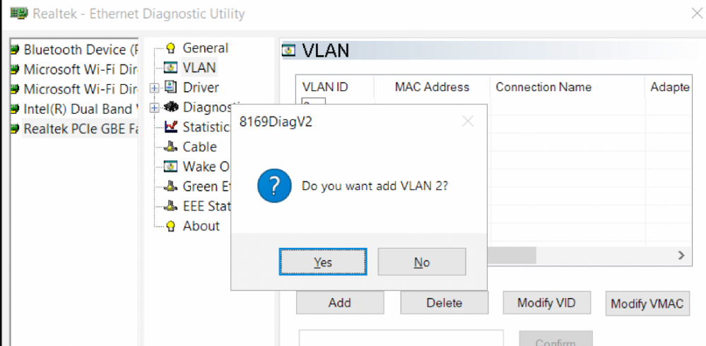
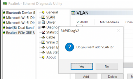
Скачайте и установите последнюю версию сетевого драйвера для вашего адаптера Realtek и запустите утилиту Realtec Ethernet Diagnostic Utility (Diagnostic Program for Win7/Win8/Win10/Win11).
Перейдите в раздел VLAN, нажмите кнопку Add и добавьте нужный VLAN ID. После этого в Windows появится новый сетевой интерфейс.
После того, как вы создали сетевые интерфейсы для ваших VLAN, вы можете задать на них нужный IP из соответствующей подсети.
Добавляем VLAN интерфейсы на сетевом адаптере Intel Ethernet
У Intel для настройки VLAN есть собственная утилита Intel Advanced Network Services (Intel® ANS) VLAN. Ваша модель сетевого адаптера, естественно, должна поддерживать технологию VLAN (например, VLAN не поддерживаются для карт Intel PRO/100 и PRO/1000). При установке драйвера выбейте опции Intel PROSet for Windows Device Manager и Advanced Network Services.
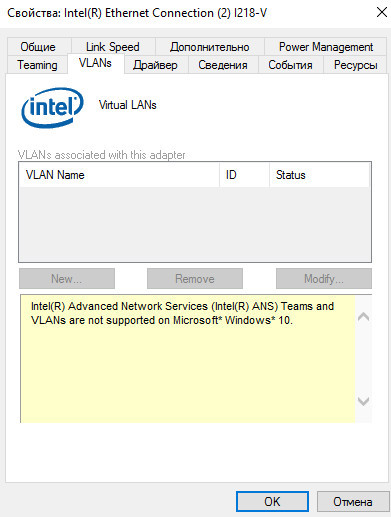
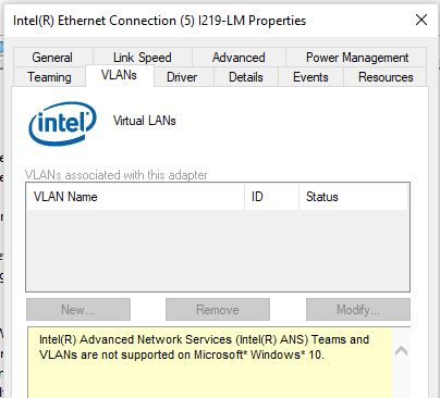
После этого в свойствах физического сетевого адаптера Intel появляется отдельная вкладка VLANs, где вы можете добавить несколько VLAN интерфейсов.
Однако этот способ работает во всех предыдущих версиях Windows (до Windows 10 1809). В последних версиях Windows на этой вкладке присутствует надпись:
Intel(R) Advanced Network (Intel(R) ANS) Teams and VLANs are not supported on Microsoft Windows 10.
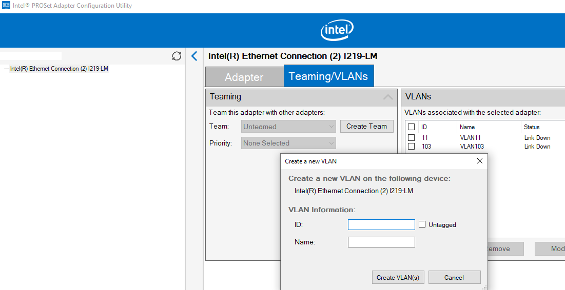
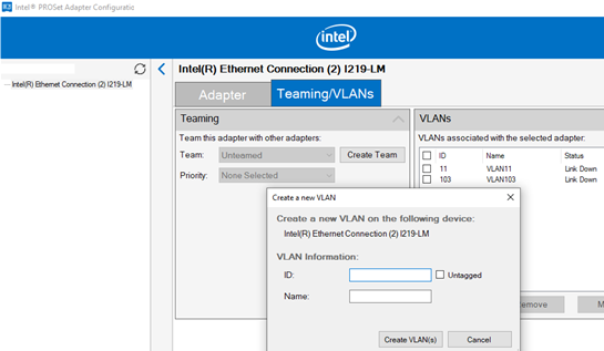
Intel недавно выпустила обновленные драйвера сетевых адаптеров и утилиту Intel PROSet Adapter Configuration Utility для последних версий Windows 10 и 11. Скачайте и установите последнюю версию драйвера Intel и утилиту Intel PROset.
Запустите утилиту, перейдите на вкладку Teaming/VLANs, нажмите кнопку New, и укажите имя сетевого интерфейса и его VLANID.
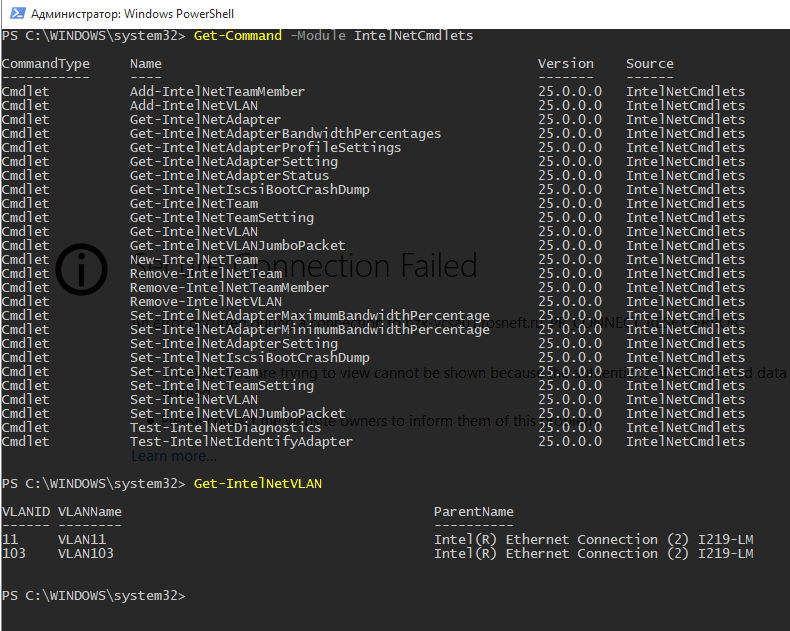
Кроме того, вы можете добавить/удалить/просмотреть список VLAN на сетевых картах Intel с помощью специальных PowerShell командлетов из модуля IntelNetCmdlets. Импортируйте модуль в свою PowerShell сессию:
Import-Module -Name "C:Program FilesIntelWired NetworkingIntelNetCmdletsIntelNetCmdlets" -Scope Local
Вы можете создать нетегированный виртуальный сетевой адаптер (обычно используется с native-vlan-id):
Add-IntelNetVLAN -ParentName "Intel(R) Ethernet Connection I219-LM" -VLANID 0
Чтобы создать сетевой адаптер Intel с конкретным номером VLAN:
Add-IntelNetVLAN -ParentName "Intel(R) Ethernet Connection I219-LM" -VLANID 11
Чтобы вывести список всех виртуальных сетевых адаптеров Intel:
Get-NetAdapter
Удалить VLAN адаптер:
Remove-IntelNetVLAN -ParentName "Intel(R) Ethernet Connection I219-LM" -VLANID 11
Для сетевых карт Broadcom вы можете создавать группы виртуальных сетевых интерфейсов и назначать им VLAN ID с помощью утилиты Broadcom Advanced Control Suite.
Добавить несколько VLAN ID в Windows Server 2019/2016
В Windows Server 2022/2019/2016/2012R2 вы можете настроить несколько VLAN на одном сетевом интерфейсе с помощью встроенных средств (без установки специальных драйверов или утилит). Попробуем настроить несколько разных VLAN на одной физической сетевой карте в Windows Server 2019 с помощью NIC Teaming.
Обязательно убедитесь, что в настройках параметров дополнительных свойств сетевого адаптера не задана VLAN (значение VLAN ID = 0). 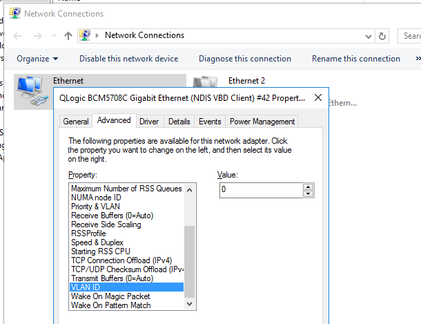
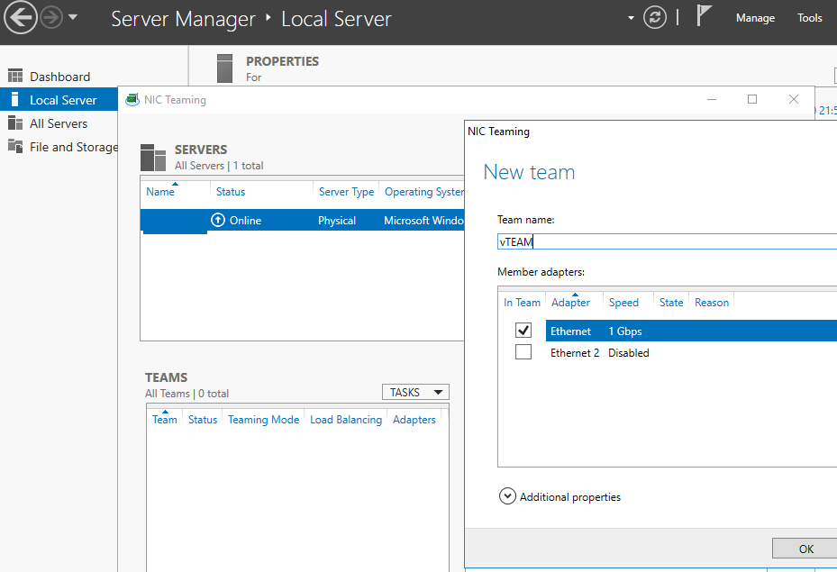
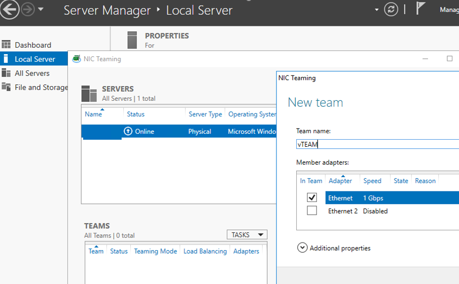
- Запустите Server Manager -> Local и нажмите на ссылку «NIC Teaming«;
- В секции Teams нажмите Task -> New Team. Укажите имя группы и выберите сетевые адаптеры, которые нужно в нее добавить;

Можно создать группу NIC Teaming с помощью PowerShell:
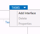
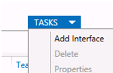
New-NetLbfoTeam -Name vTeam -TeamMembers "Ethernet1","Ethernet2" -TeamingMode SwitchIndependent -LoadBalancingAlgorithm Dynamic - Теперь в секции «Adapter and Interfaces» можно добавить виртуальные сетевые интерфейсы. Нажмите Tasks -> Add Interface;

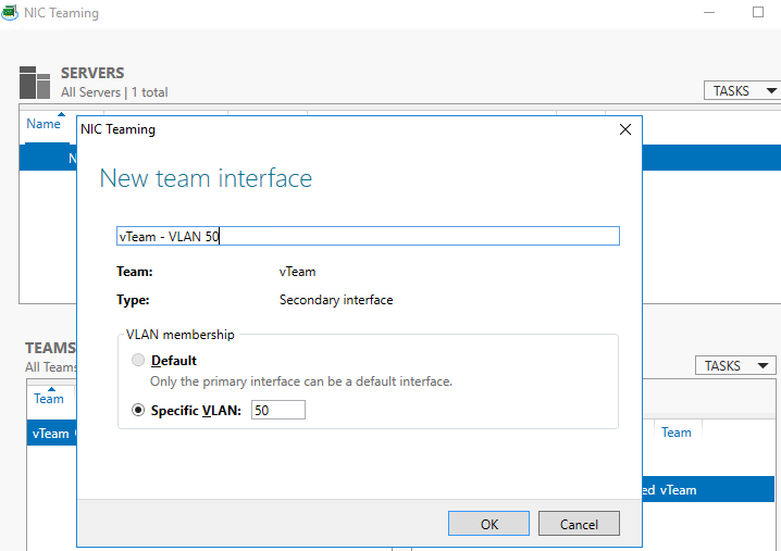
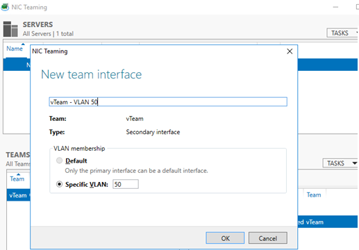
- Укажите имя создаваемого интерфейса и номер VLAN;

Из PowerShell добавить сетевой интерфейс и задать ему VLAN можно так:
Add-NetLbfoTeamNic -Team vTeam -VlanID 50 -Name VLAN50 - Аналогичным образом можно добавить столько сетевых интерфейсов VLAN, сколько нужно;
Обратите внимание, что в Windows Server 2022/2019/2016 поддерживает не более 32 сетевых адаптеров (и соответственно уникальных VLAN) для одной группы NIC Teaming.
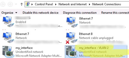
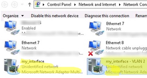
- Для каждого сетевого интерфейса в панели управления сетевыми адаптерами (ncpa.cpl) появится отдельная виртуальная сетевая карта;

- Теперь вы можете настроить IP параметры всех созданных виртуальных VALN сетевых интерфейсов вручную в свойствах адаптера или с помощью PowerShell командлетов New-NetIPAddress и Set-DnsClientServerAddress:
New-NetIPAddress -InterfaceAlias my_VLAN_interface -IPAddress 192.168.30.30 -PrefixLength 24 -DefaultGateway 192.168.30.1
Set-DnsClientServerAddress -InterfaceAlias my_VLAN_interface -ServerAddresses 192.168.1.10
Как создать несколько VLAN в Windows Hyper-V?
Вы можете программно обрабатывать VLANы в Windows через через подсистему Hyper-V (доступно как в Windows Server, так и десктопных Windows 10/11 Pro и Enterprise редакциях). Вы можете создать виртуальный свитч с сетевым адаптером в определённом VLAN.
Для этого нужно установить компоненты Hyper-V:
Enable-WindowsOptionalFeature -Online -FeatureName:Microsoft-Hyper-V -All
Создайте новый виртуальный коммутатор через Hyper-V Manager или с помощью команд PowerShell (см. пример в статье о настройке Hyper-V Server).
Затем для каждого VLAN, который нужно создать, выполнить команды:
Add-VMNetworkAdapter -ManagementOS -Name VLAN50 -StaticMacAddress "11-22-33-44-55-AA" -SwitchName VLAN50Switch
Set-VMNetworkAdapterVlan -ManagementOS -VMNetworkAdapterName VLAN50 -Access -VlanId 50
В результате у вас в системе появится сетевой адаптер с нужным тегом VLAN.
Если на вашем Hyper-V сервере запущены ВМ, вы можете поместить их в разные VALN. Чтобы переключить виртуальны сетевой адаптер ВМ на Hyper-V в режим Access и разрешить получать трафик только с определенным VLAN ID, используется команда:
Set-VMNetworkAdapterVlan -VMName Test1 -Access -VlanId 21
Вывести список ВМ и назначенных им VLAN:
Get-VMNetworkAdapterVLAN
В Windows Server 2022 с ролью Hyper-V вы не сможете привязать виртуальный свитч к такому тиминг-интерфейсу. Дело в том, что что LBFO NIC Teaming устарел (https://aka.ms/lbfodeprecation) и в Windows Server 2022 предлагается использовать Switch Embedded Teaming (SET).
Рассмотрим, как создать виртуальный адаптер и назначить ему VLAN в Windows Server 2022 Hyper-V с помощью SET.
Создайте виртуальный свитч, подключённый к сетевым адаптерам хоста:
New-VMSwitch -Name "HVSwitch1" -NetAdapterName "Ethernet3","Ethernet4" -EnableEmbeddedTeaming $true
Теперь создайте виртуальны адаптер, подключенный к виртуальному свитчу:
Add-VMNetworkAdapter -ManagementOS -Name "VLAN11" -StaticMacAddress "XX-XX-XX-XX-XX-XX" -SwitchName "HVSwitch1"
Назначьте тег VLAN для вашего виртуального адаптера:
Set-VMNetworkAdapterVlan -ManagementOS -VMNetworkAdapterName "VLAN11" -Access -VlanId 11
Если нужно, чтобы виртуальный адаптер Hyper-V мог принимать пакеты из нескольких VLAN, можно использовать такую команду:
Get-VMNetworkAdapter -Name youradaptername | Set-VMNetworkAdapterVlan -Trunk -AllowedVlanIdList 50-59 -NativeVlanId 0
Параметр -NativeVlanId 0 обязателен. В этом случае мы указываем Hyper-V, что VLAN:0 используется в качестве нативного для нетегированного трафика.
Одной из главных компонент нового Hyper-V в Windows Server 2012 является Hyper-V Extensible Switch. Hyper-V Extensible Switch представляет собой программный управляемый коммутатор второго уровня, обладающий рядом интересных возможностей, среди которых поддержка технологии Private VLAN (PVLAN). Я вкратце опишу реализацию PVLAN в свиче Hyper-V и в большей степени сосредоточусь на вопросах настройки частных VLAN-ов для виртуальных машин (ВМ). Посмотреть технологию в действии вы можете в первой демонстрации веб-каста, посвященного новым возможностям Hyper-V в Windows Server 2012.
Суть PVLAN-ов уже обсуждалась на Хабре, в частности здесь. Применительно к Hyper-V вы можете присвоить каждому порту Hyper-V Extensible Switch один основной (первичный или Primary VLAN ID) идентификатор и один или несколько вторичных (Secondary VLAN ID). В отличие от аппаратного свича с конкретным количеством портов, порт на свиче Hyper-V идентифицируется виртуальной машиной, а еще точнее сетевым адаптером (поскольку их может быть несколько) виртуальной машины, подключенным к этому порту. Поэтому здесь и далее, задать настройки для порта Hyper-V Extensible Switch = задать настройки для соответствующей виртуальной машины.
Итак, при настройке PVLAN-ов и указании Primary и Secondary VLAN ID соответствующий порт может быть сконфигурирован в одном из трех режимов:
- promiscuous (смешанный) – в этом режиме ВМ может обмениваться пакетами с любыми портами у которых совпадает Primary VLAN ID;
- community (общий) – в этом режиме ВМ может обмениваться пакетами с любыми другими портами, сконфигурированными в community режиме, у которых совпадают и Primary, и Secondary VLAN ID; кроме того (см. выше), ВМ может взаимодействовать с promiscuous-портами, у которых такой же Primary VLAN ID;
- isolated (изолированный) – в этом режиме ВМ может взаимодействовать только с promiscuous- портами c таким же Primary VLAN ID.
Кроме того надо отметить, что Hyper-V Extensible Switch переводит в режим trunk порт, который «смотрит» на физический сетевой адаптер хоста. При условии, что ваши аппаратные свичи не блокируют тегированные пакеты, логика работы рассмотренных режимов не зависит от того, запущены ли ВМ на одном физическом хосте с Windows Server 2012 или на разных.
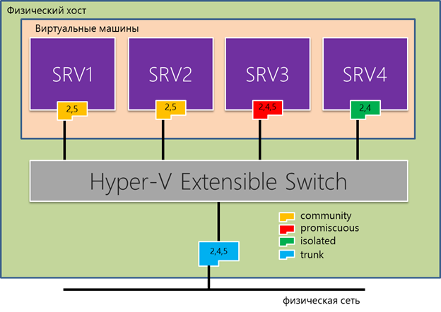
Одним из основных вариантов применения PVLAN является дополнительная изоляция ВМ, запущенных в вашем ЦОД-е и принадлежащих разным отделам, департаментам или организациями. Поясню на примере. Предположим, на одном хосте запущено четыре ВМ (см. рис. ниже). SRV1 и SRV2 принадлежат, скажем, отделу продаж, в них запущены какие-либо компоненты приложения, например в одной SharePoint, в другой SQL Server с базой данных SharePoint. SRV4 принадлежит финансовому департаменту и должна быть изолирована от ВМ других отделов. Наконец, в SRV3 запущены сервисы, которые необходимы всем ВМ данного хоста или нескольких хостов. Возможный вариант решения этой задачи с помощью PVLAN:
- Конфигурируем SRV1 и SRV2 в community-режиме с Primary VLAN ID = 2 и Secondary VLAN ID = 5; разумеется, конкретные значения идентификаторов определяете вы сами;
- Конфигурируем SRV4 в режиме isolated с Primary VLAN ID = 2 и Secondary VLAN ID = 4;
- Конфигурируем SRV3 в режиме promiscuous с Primary VLAN ID = 2 и Secondary VLAN ID = 4 и 5.
Теперь давайте реализуем эту задачу в Windows Server 2012. Начнем с SRV4. Настройка PVLAN осуществляется командлетами PowerShell. Как отмечалось, порт свича Hyper-V идентифицируется сетевым адаптером ВМ, подключенной к этому порту. Проще всего получить информацию о сетевых адаптерах ВМ с помощью команды Get-VMNetworkAdapter, указав в качестве параметра имя ВМ:

Как видно, в SRV4 существует единственный сетевой адаптер с именем, совпадающим с именем самой виртуальной машины – SRV4. Текущие настройки VLAN соответствующего порта Hyper-V Extensible Switch можно увидеть с помощью Get-VMNetworkAdapterVlan:
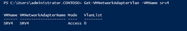
Сейчас SRV4 находится в режиме Access с единственным VLAN ID, равным нулю. Это настройка по умолчанию для ВМ равносильная тому, что нет вообще никаких VLAN-ов. И в таком же состоянии находятся пока все остальные ВМ: SRV1, SRV2, SRV3. Включаем нужный нам режим для SRV4 командой Set-VMNetworkAdapterVlan:
Set-VMNetworkAdapterVlan -VMName srv4 -VMNetworkAdapterName srv4 -Isolated -PrimaryVlanId 2 -SecondaryVlanId 4Параметрами -VMName и -VMNetworkAdapterName указываем имена ВМ и сетевого адаптера соответственно, остальными параметрами указываем режим и Primary и Secondary VLAN ID. Проверяем настройки:
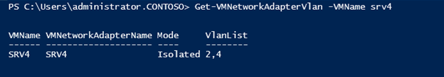
Обратите внимание, что начиная с этого момента, SRV4 не может взаимодействовать с другими ВМ, пока мы не настроим должным образом PVLAN и для них. Сделаем это соответствующими командами, используя конвейер команд PowerShell, где результат выполнения одной команды передается на вход следующей:
Get-VMNetworkAdapterVlan -VMName srv3 | Set-VMNetworkAdapterVlan -Promiscuous -PrimaryVlanId 2 -SecondaryVlanIdList 4-5
Get-VMNetworkAdapterVlan -VMName srv2 | Set-VMNetworkAdapterVlan -Community -PrimaryVlanId 2 -SecondaryVlanId 5
Get-VMNetworkAdapterVlan -VMName srv1 | Set-VMNetworkAdapterVlan -Community -PrimaryVlanId 2 -SecondaryVlanId 5
Замечу, что в первой команде список Secondary VLAN ID задан диапазоном. Кроме того, можно задать различные значения идентификаторов, перечислив их через запятую и заключив в кавычки: -SecondaryVlanIdList “4,5”.
В любой момент можно вернуть настройки в исходное состояние, например для SRV4 выполнив:

В заключение, несколько слов о режиме trunk. Как я упоминал выше, Hyper-V переводит в режим trunk порт, к которому подключен физический сетевой адаптер. Но если необходимо, в trunk-режим можно переключить любую ВМ, чтобы она могла принимать пакеты с различными VLAN ID. Для все той же SRV4 команда будет выглядеть как:

Здесь -AllowedVlanIdList задает список разрешенных VLAN ID, как Primary, так и Secondary, а параметр -NativeVlanId указывает, к какому VLAN-у будут относиться нетегированные пакеты.
Таким образом, поддержка технологии PVLAN наряду с другими возможностями Hyper-V Extensible Switch поможет обеспечить дополнительный уровень изоляции ВМ в рамках мультитенантной архитектуры.
Дополнительную информацию вы сможете найти на портале Microsoft Virtual Academy.
Но лучший, с моей точки зрения, источник информации — сам продукт, который можно скачать и попробовать перечисленные возможности на практике.
In this article, we’ll show how to configure a tagged VLAN interface on Windows 10/11 and Windows Server 2019 (2022/2016/2012R2). The VLAN (Virtual LAN) specification is described in the IEEE 802.1Q standard and involves marking traffic with tags (vlanid) so that a network packet may be referred to a particular virtual network. VLANs are used to separate and segment networks, restrict broadcast domains, and isolate network segments to improve security. On Windows, you can configure multiple logical network interfaces with different VLAN ID on a single physical NIC using different tools.
Contents:
- Creating Multiple VLAN Interfaces on Windows 10 and 11
- How to Configure Multiple VLANs on Windows Server 2022/2019/2016?
- Create Multiple VLANs with Windows Hyper-V Role
In order to use VLAN on Windows, you need to reconfigure the physical switch port to which your computer/server is connected to. The port must be switched from access mode to trunk mode. By default, all VLANs are allowed on a trunk port, but you can set the list of allowed VLAN numbers (1 to 4094) available at this Ethernet switch port.
Creating Multiple VLAN Interfaces on Windows 10 and 11
Windows desktop editions don’t natively support VLAN tagging. By default, most network adapter drivers ignore all VLAN tags in network packets and external VLANs become inaccessible.
For some network adapters, you can set the VLAN number in the driver properties:
- Run the Device Manager (
devmgmt.msc); - Expand the Network adapters section and open the properties of your network adapter;
- Go to the Advanced tab and find the VLAN ID option;

- You can set the VLAN number here;
- For some NICs, you first need to enable the Packet Priority and VLAN option.

In modern versions of Windows 10 and 11, you can set one VLAN tag for a network interface adapter. You can use PowerShell to manage network settings. For example, you want to set VLAN ID 24 for your network interface named Ethernet0:
Set-NetAdapter –Name "Ethernet0" -VlanID 24
For some NICs (from Intel, Broadcom, HP, Realtek), special tools are available that allow you to create a virtual network interface in Windows with a VLAN ID. To do this, you need to install a special driver on your computer that supports 802.1Q tagged traffic and the official configuration tool from the vendor.
Create Multiple VLANs on a Realtek NIC in Windows 10 or 11
For Realtek NICs, you can configure multiple virtual NICs with different VLANs using the Realtek Ethernet Diagnostic Utility. Find the description of your Realtek network controller on the vendor’s website, and check that this model supports VLAN. For example, the specification for the RTL8169SC(L) network controller has this option:
Supports IEEE 802.1Q VLAN tagging
Download and install the latest network driver for your Realtek adapter and run the Realtek Ethernet Diagnostic Utility (Diagnostic Program for Win7/Win8/Win10/Win11).
Go to the VLAN section, click Add and add the required VLAN ID. After that, a new network interface will appear in Windows.
After creating network interfaces for your VLANs, you can assign the IP addresses from the corresponding IP network.
How to Setup VLAN on an Intel Ethernet Network Adapter?
Intel has its own Intel Advanced Network Services (Intel® ANS) tool for configuring VLAN interfaces. Your network adapter model, of course, must support VLAN (for example, VLAN is not supported for NICs such as Intel PRO/100 or PRO/1000). When installing the driver, select the Intel PROSet for Windows Device Manager and Advanced Network Services options.
Then a separate VLANs tab appears in the properties of your physical Intel network adapter, where you can create multiple VLAN interfaces.
However, this method works on all previous versions of Windows (up to Windows 10 1809). In modern Windows 10/11 builds, the following message is displayed in the VLANs tab:
Intel(R) Advanced Network (Intel(R) ANS) Teams and VLANs are not supported on Microsoft Windows 10.
Intel recently released new network adapter drivers and the Intel PROSet adapter configuration tool for the latest builds of Windows 10 and 11. Download and install the latest Intel driver and Intel PROset utility.
Run the configuration tool, go to the Teaming/VLANs tab, click the New button, and specify the name of the network interface and its VLANID.
In addition, you can add/remove/view the list of VLANs on Intel NICs using the PowerShell cmdlets from the IntelNetCmdlets module. Import the module into your PowerShell session:
Import-Module -Name "C:Program FilesIntelWired NetworkingIntelNetCmdletsIntelNetCmdlets" -Scope Local
You can create an untagged virtual network adapter (usually used with native-vlan-id):
Add-IntelNetVLAN -ParentName "Intel(R) Ethernet Connection I219-LM" -VLANID 0
To create an Intel NIC with a specific VLAN number:
Add-IntelNetVLAN -ParentName "Intel(R) Ethernet Connection I219-LM" -VLANID 103
To list all virtual Intel network adapters:
Get-NetAdapter
Remove VLAN interface:
Remove-IntelNetVLAN -ParentName "Intel(R) Ethernet Connection I219-LM" -VLANID 103

For Broadcom NICs, you can create groups of virtual network interfaces and assign VLAN IDs using the Broadcom Advanced Control Suite tool.
How to Configure Multiple VLANs on Windows Server 2022/2019/2016?
In Windows Server 2022/2019/2016/2012R2, you can configure multiple VLANs on the same network interface using built-in tools (without installing third-party drivers and tools). Let’s try to configure multiple VLANs on the same physical NIC in Windows Server 2019 using NIC Teaming.
Make sure that no VLAN number is set in the network adapter advanced settings (VLAN ID = 0). 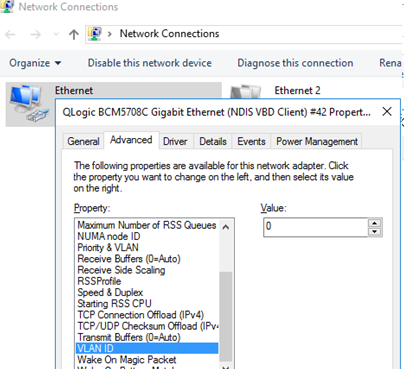
- Open the Server Manager -> Local and click the NIC Teaming link;
- In the Teams section, click Task -> New Team. Specify the group name and select network adapters to add;
You can create a NIC Teaming group using PowerShell:
New-NetLbfoTeam -Name vTeam -TeamMembers "Ethernet1","Ethernet2" -TeamingMode SwitchIndependent -LoadBalancingAlgorithm Dynamic - Then in the “Adapter and Interfaces” section, add virtual network interfaces. Click Tasks -> Add Interface;
- Enter the name of the interface you are going to create and a VLAN number;
You can add a network interface and set a VLAN for it in PowerShell:
Add-NetLbfoTeamNic -Team vTeam -VlanID 24 -Name VLAN24 - In the same way, you can add as many VLAN network interfaces as you need;
Please note that Windows Server 2022/2019/2016 supports a maximum of 32 NICs (and unique VLANs) per NIC Teaming group.
- A separate virtual network adapter will appear in the list of network connections in
ncpa.cpl;
- Now you can configure the IP settings for each VLAN interface in the properties of the network adapter or using PowerShell cmdlets:
New-NetIPAddress -InterfaceAlias your_VLAN_interface -IPAddress 192.168.10.10 -PrefixLength 24 -DefaultGateway 192.168.10.1

Set-DnsClientServerAddress -InterfaceAlias your_VLAN_interface -ServerAddresses 192.168.100.12
Create Multiple VLANs with Windows Hyper-V Role
You can programmatically handle multiple VLANs in Windows through the Hyper-V subsystem (available in both Windows Server and desktop Windows 10/11 Pro and Enterprise editions). You can create a virtual switch with a network adapter in a specific VLAN.
To do this, you need to install Hyper-V components:
Enable-WindowsOptionalFeature -Online -FeatureName:Microsoft-Hyper-V -All
Create a new virtual switch through Hyper-V Manager or using PowerShell commands (see an example in the article on how to configure Hyper-V Server).
Then run the following commands for each VLAN you want to create:
Add-VMNetworkAdapter -ManagementOS -Name VLAN24 -StaticMacAddress "11-11-AA-BB-CC-DD" -SwitchName vSwitch2

Set-VMNetworkAdapterVlan -ManagementOS -VMNetworkAdapterName VLAN24 -Access -VlanId 24
So a network adapter with the VLAN you want will appear in Windows.
If you have VMs running on your Hyper-V server, you can put them in different VLANs. To switch the virtual network adapter of a VM on Hyper-V to Access mode and allow it to receive traffic only with a specific VLAN ID, use the command:
Set-VMNetworkAdapterVlan -VMName MyVMName1 -Access -VlanId 30
Display a list of VMs and their assigned VLANs:
Get-VMNetworkAdapterVLAN
In Windows Server 2022 with the Hyper-V role, you won’t be able to bind a virtual switch to such a teaming interface. The fact is that LBFO NIC Teaming is a deprecated feature on Windows Server 2022 (https://aka.ms/lbfodeprecation). Instead of NIC Teaming, it is proposed to use Switch Embedded Teaming (SET).
Let’s create a virtual adapter and assign a VLAN to it on Windows Server 2022 Hyper-V using SET.
Create a virtual switch connected to the host’s physical adapters:
New-VMSwitch -Name HVVLANSwitch1 -NetAdapterName "Ethernet3","Ethernet4" -EnableEmbeddedTeaming $true
Now create a virtual adapter connected to the virtual switch:
Add-VMNetworkAdapter -ManagementOS -Name "VLAN22" -StaticMacAddress "XX-XX-XX-XX-XX-XX" -SwitchName HVVLANSwitch1
Assign a VLAN tag to your virtual adapter:
Set-VMNetworkAdapterVlan -ManagementOS -VMNetworkAdapterName "VLAN22" -Access -VlanId 22
You can enable the virtual Hyper-V adapter to receive packets from multiple VLANs using the command:
Get-VMNetworkAdapter -Name youradaptername | Set-VMNetworkAdapterVlan -Trunk -AllowedVlanIdList 40-69 -NativeVlanId 0
The -NativeVlanId 0 parameter is required. In this case, we tell Hyper-V that VLAN:0 is used as native for untagged traffic.
Network segmentation is a great way to compartmentalize the various networks you need to run in your environment. This provides many benefits from both a management and security perspective. When segmenting your networks, one of the things that you have to consider and take care of is IP addressing. Dynamic Host Configuration Protocol (DHCP) is an age-old standard that has been used in the enterprise for handing out IP addresses to clients on the network. DHCP requires its own broadcast domain, which in turn requires VLANs. Many organizations are using Windows Server for DHCP on their networks. In this post, we will take a look at Windows Server DHCP VLAN configuration. These steps work for Windows Server 2012, 2016, 2019, and Windows Server 2022.wind
Why are VLANs needed for DHCP?
When a client is provisioned on a network segment and is set up to have IP addressing configured automatically using DHCP, the client makes broadcast queries on the network segment to notify the DHCP server configured that it needs an IP address. The DHCP server responds with the appropriate IP address for the network segment and the additional configuration for network connectivity on the segment.
VLANs (Virtual Local Area Networks) allow taking a physical network switch and logically segmenting the physical network environment into multiple network segments. This makes much more efficient use of network hardware since additional segments do not require additional physical network switches. By introducing VLANs, you can provision multiple network segments on the same switch.
When you spin up a new network segment IP address range, you want to pair this with a new VLAN or logical network segment. VLANs control broadcast ranges. Within each VLAN, clients can initiate the broadcast for a network IP address from a DHCP server. There are many different ways to have a Windows Server participate in a VLAN network segment. Before we look at the specifics related to DHCP VLAN configuration, let’s take a look at the multiple options for connecting the Windows host into a VLAN-backed network.

Connecting Windows Server to Multiple VLANs
There are many different ways to connect Windows Server to multiple VLANs. This includes the following:
- Additional network interfaces Untagged for VLAN traffic
- A single network interface with Tagged VLAN frames
- Routed Layer 3 connectivity to VLAN-backed subnets
Additional network interfaces Untagged for VLAN traffic
With VLANs, you hear two different terms tossed out there related to the VLAN you are working with – untagged, and tagged. When you talk about untagged frames, this means the Windows host is not tagging the Ethernet frames originating from the host with VLAN information. Instead, it is relying on the upstream switch it is plumbed into to handle that configuration.
So, essentially, the Windows Server is unaware of the VLAN and doesn’t care. It simply relies on its physical uplink to do any VLAN tagging for it to communicate appropriately. However, this means that if you want to have a Windows Server to be a part of multiple VLANs, it means you need a physical uplink for each separate VLAN, since it is relying on the switch to tag the traffic appropriately for a specific VLAN.
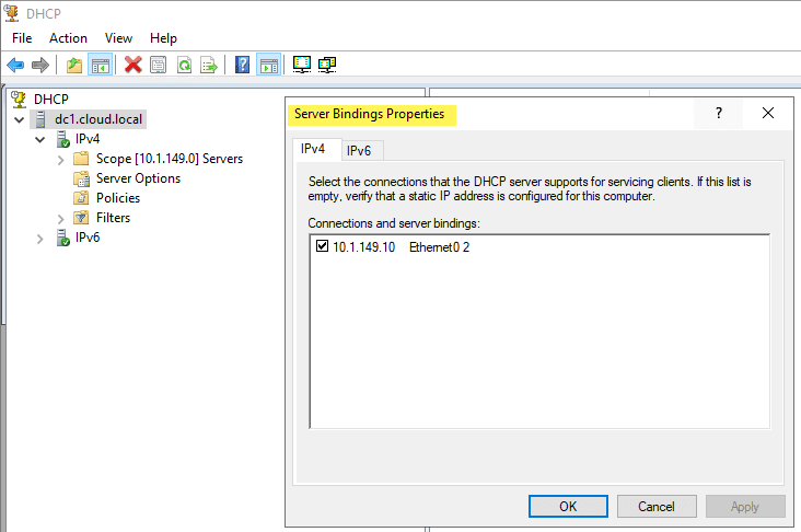
As shown below on a Windows Server 2019 server, you can specify the Bindings for the Windows DHCP Server so that it knows which interfaces to “listen” for DHCP on.
A single network interface with Tagged VLAN frames
While there may be reasons that you use multiple physical uplinks with untagged frames for communicating with different VLANs, a more efficient approach is to use Tagged VLAN frames on a single network connection. When you use tagged frames, the Windows Server tags the frames appropriately for each VLAN it is associated with. The ability to Tag frames generally needs vendor-specific driver sets to be loaded, such as the Intel Pro Set drivers using Intel-based cards.
Routed Layer 3 connectivity to VLAN-backed subnets
The third option is simply relying on routing to take care of connectivity to the VLAN-backed subnets they need to communicate with. This technically does not connect the Windows Server into the VLAN as that would mean it would have the ability to be in the broadcast domain which is a Layer 2 VLAN construct. Instead, you are relying on Layer 3 connectivity to IP addresses. For many type of communication, including Windows Server 2012 DHCP VLAN configuration, this is all that is needed.
You can use all three of the methods above for Windows Server 2012, 2016, 2019, and Windows Server 2022 DHCP VLAN configuration. You can add multiple network adapters to each VLAN and have each scope listen on that specific network interface for DHCP requests. You can also use the tagging method listed above that allows adding multiple VLANs to a single network interface which allows keeping a single network adapter and connecting that physical network uplink to multiple VLANs.
You might assume the third option, since it is not connecting the uplink to the physical broadcast domain, would not be able to answer the broadcast DHCP request from the client on a specific VLAN. However, even though the DHCP server is not on the same broadcast domain/VLAN, there are really only two pieces of information the DHCP servers need to know to allocate an IP address on a particular subnet. This includes:
- Source subnet of the client
- MAC address of the client
You will note that the Windows Server DHCP server being a part of the VLAN is not a requirement for a successful DHCP request being made to the Windows Server. The third option is typically the option that I steer towards unless there are requirements for multiple physical uplinks for compliance or other security-based reasons. So, how does the Windows DHCP Server respond to a DHCP broadcast request if it is not on the same VLAN to take part in the broadcast traffic?
IP Helper Address, DHCP Relay, DHCP Proxy Address
This is made possible by the IP Helper Address which is sometimes referred to as DHCP Relay, or DHCP proxy address. Using an IP helper address, DHCP Relay, or DHCP proxy address allows the special DHCP broadcast messages to be forwarded from VLAN they originated from and forwarded to the DHCP server. This role is typically handled by a firewall or router device that is able to take the DHCP broadcast message and forward these to the DHCP server.
How does this work? When the DHCP client issues the DHCP broadcast request packet, is as of yet has no IP address configured. This being the case, it uses a broadcast with an all zero source address – 0.0.0.0. It also has no way to get to the DHCP Server with the lack of IP configuration. With this being the case, the client uses a general broadcast address of 255.255.255.255 as the destination with the DHCP request packet.
The device handling the DHCP proxy functionality receives the DHCP request packet from the client, replaces the destination address of 255.255.255.255 with the configured address of the server that was configured in the IP helper-address configuration. The client’s MAC address is included in the DHCP request so the receiving DHCP server knows the required MAC address of the client. This information is then forwarded to the DHCP server from the router, firewall, or another device in the role of the DHCP proxy.
The DHCP server issues an address now that it knows the subnet the client resides on along with the MAC address. It sends the DHCP response back to the DHCP Proxy device. The DHCP Proxy device then forwards the response to the correct MAC address of the requesting client and it is able to be configured with the IP address allowing network communication on the subnet.
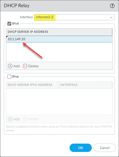
The configuration of DHCP Relay is generally simple but can vary depending on the vendor of router, firewall, or other device you might be using to perform this function. Below is the configuration of DHCP Relay on a Palo Alto firewall. You simply have to select the Interface and the DHCP Server IP Address you want to use for the target of DHCP requests.
Windows Server DHCP VLAN configuration for Virtual Machine DHCP servers
The principles still apply to Windows Server DHCP servers running inside a Windows Server virtual machine. The one method that is more difficult is the tagging of a single interface with multiple VLANs as this is not a feature that you can carry out with VMware Tools drivers that I am aware of. You can add multiple virtual NICs to a single VM and connect the virtual machine to different VLAN-backed port groups for each connection.
This will essentially place the Windows Server virtual machine on the same network segments as the clients that need addresses. Or, you can use the preferred method of using an IP Helper Address to forward the DHCP requests from all the other VLAN-backed subnets to the DHCP server and have the addresses issued by the server using only the single network connection.
Creating a Windows Server DHCP scope for a different VLAN
As detailed by the explanation above, the actual work of the Windows Server DHCP VLAN configuration takes place with the IP Helper Address/DHCP proxy device. Creating a Windows Server DHCP scope for a different VLAN is the same as creating a scope for the native VLAN network where the DHCP Server itself is located. Non-intuitively, you won’t see any part of the scope creation wizard that has you define the VLAN configuration. However, this is not needed in any of the configurations mentioned. With IP Helper Address, the packets are forwarded by the DHCP proxy to the DHCP server. If you are using different interfaces or tagged interfaces, the DHCP server will receive the DHCP broadcasts as normal.
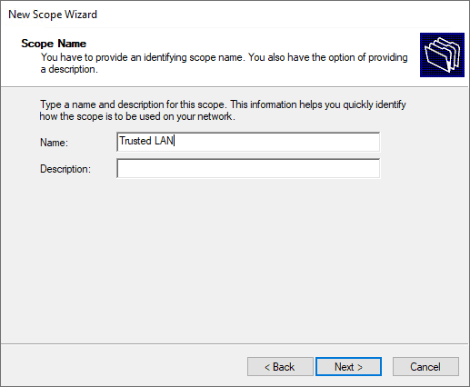
Set the name and description (optional) of the new DHCP scope.
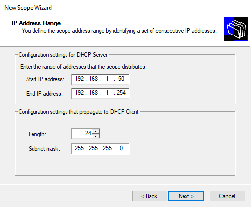
Specify the new DHCP address range.
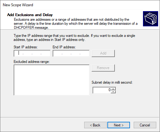
Set the exclusion range for the DHCP scope.
Specify the lease duration.
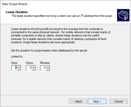
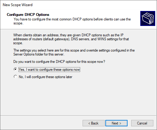
Configure the DHCP options for the new DHCP scope.
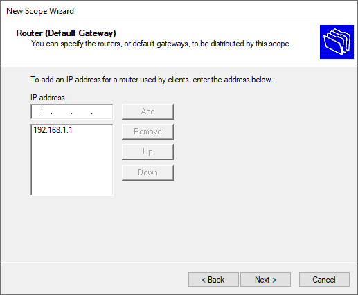
Define the default gateway of the new Windows Server DHCP VLAN configuration.
Configure domain name and DNS servers.
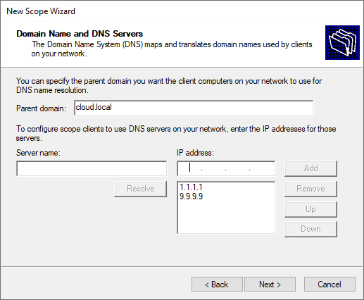
Setup any WINS server addresses.
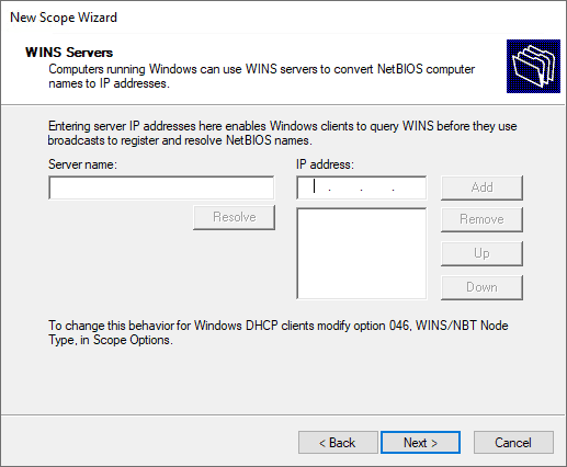
Activate the new DHCP scope.
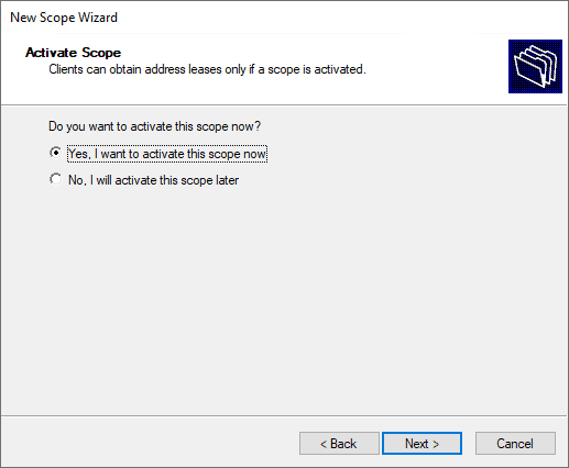
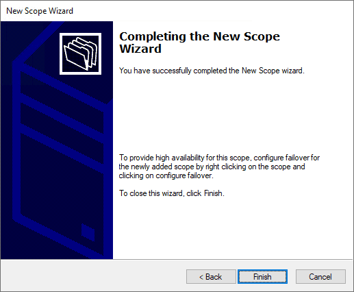
Complete the new DHCP scope wizard.
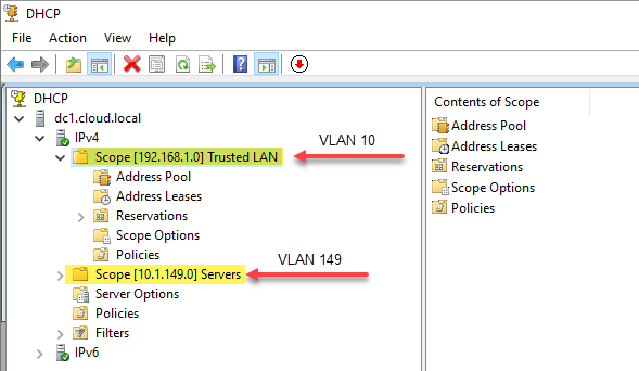
Below is an example of how my DHCP server looks after creating two different scopes for address leasing.
- 192.168.1.0/24 – associated with VLAN 10, which is not where the Windows Server DHCP server resides.
- 10.1.149.0/24 – associated with VLAN 149. This is the VLAN where the DHCP server resides.
Wrapping Up
Hopefully, this Windows Server DHCP VLAN Configuration: Detailed Guide will help any who may be trying to wrap their heads around the configuration of DHCP services for different VLANs and network segments in their network. By understanding the different means you have available to hand out IP addresses from a Windows DHCP Server you can effectively segment your network and easily handle IP addressing for all clients in the network, regardless of the VLAN they reside on.
With Server virtualization you can run multiple server instances concurrently on a single physical host; yet servers are isolated from each other and operate independently. Similarly Network virtualization provides multiple virtual network infrastructures run on the same physical network with or without overlapping IP addresses. Each virtual network infrastructure operates as if they are the only virtual network running on the shared network infrastructure. Hyper-v Network Virtualization also decouples physical network from virtual network. Network virtualization can be achieved via System Center Virtual Machine Manager (SCVMM) managing multiple Hyper-v Servers, a single Hyper-v Server or clustered Hyper-v Servers. Microsoft Hyper-v Network Virtualization provides multi-tenant aware, multi-VLAN aware and non-hierarchical IP address assignment to virtual machines in conventional on-premises and cloud based data center.
Hyper-v Virtual Network Type
- Private Virtual Network Switch allows communication between virtual machines connected to the same virtual switch. Virtual Machines connected to this type of virtual switch cannot communicate with Hyper-V Parent Partition. You can create any number of Private virtual switches.
- Internal Virtual Network Switch can be used to allow communication between virtual machines connected to the same switch and also allow communication to the Hyper-V Parent Partition. You can create any number of internal virtual switches
- External Virtual Network Switch allows communication between virtual machines running on the same Hyper-V Server, Hyper-V Parent Partition and Virtual Machines running on the remote Hyper-V Server. It requires a physical network adapter on the Hyper-V Host that is not mapped to any other External Virtual Network Switch. As a result, you can create External virtual switches as long as you have physical network adapters that are not mapped to any other external virtual switches.
Follow the guide lines to configure Virtual Networking in Windows Server 2012 R2 Hyper-v role installed. A highly available clustered Hyper-v server should have the following configuration parameters.
Example VLAN
| Network Type | VLAN ID | IP Addresses |
| Default | 1 | 10.10.10.1/24 |
| Management | 2 | 10.10.20.1/24 |
| Live Migration | 3 | 10.10.30.1/24 |
| Prod Server | 4 | 10.10.40.1/24 |
| Dev Server | 5 | 10.10.50.1/24 |
| Test Server | 6 | 10.10.60.1/24 |
| Storage | 7 | 10.10.70.1/24 |
| DMZ | 99 | 192.168.1.1/24 |
Example NIC Configuration with 8 network card (e.g. 2x quad NIC card)
| Virtual Network Name | Purpose | Connected Physical Switch Port | Virtual Switch Configuration |
| MGMT | Management Network | Port configured with VLAN 2 | Allow Management Network ticked
Enable VLAN identification for management operating system ticked |
| LiveMigration | Live Migration | Port configured with VLAN 3 | Allow Management Network un-ticked
Enable VLAN identification for management operating system ticked |
| iSCSI | Storage | Port configured with VLAN 7 | Allow Management Network un-ticked
Enable VLAN identification for management operating system ticked |
| VirtualMachines | Prod, Dev, Test, DMZ | Port configured with Trunk Mode | Allow Management Network un-ticked
Enable VLAN identification for management operating system un-ticked |
Recommendation:
- Do not assign VLAN ID in NIC Teaming Wizard instead assign VLAN ID in Virtual Switch Manager.
- Configure virtual switch network as External Virtual Network.
- Configure Physical Switch Port Aggregation using EtherChannel.
- Configure Logical Network Aggregation using NIC Teaming Wizard.
- Enable VLAN ID in Virtual Machine Settings.
Example Virtual Machine Network Configuration
| Virtual Machine Type | VLAN ID Tagged in VM>Settings>Network Adapter | Enable VLAN identifier | Connected Virtual Network |
| Prod VM | 4 | Ticked | VirtualMachines |
| Dev VM | 5 | Ticked | VirtualMachines |
| Test VM | 6 | Ticked | VirtualMachines |
| DMZ VM with two NICs | 4, 99 | Ticked | VirtualMachines |
NIC Teaming with Virtual Switch
Multiple network adapters on a computer to be placed into a team for the following purposes:
- Bandwidth aggregation
- Traffic failover to prevent connectivity loss in the event of a network component failure
There are two basic configurations for NIC Teaming.
- Switch-independent teaming. This configuration does not require the switch to participate in the teaming. Since in switch-independent mode the switch does not know that the network adapter is part of a team in the host, the adapters may be connected to different switches. Switch independent modes of operation do not require that the team members connect to different switches; they merely make it possible.
- Switch-dependent teaming. This configuration that requires the switch to participate in the teaming. Switch dependent teaming require participating NIC to be connected in same physical switch. There are two modes of operation for switch-dependent teaming: Generic or static teaming (IEEE 802.3ad draft v1). Link Aggregation Control Protocol teaming (IEEE 802.1ax, LACP).
Load Balancing Algorithm
NIC teaming in Windows Server 2012 R2 supports the following traffic load distribution algorithms:
- Hyper-V switch port. Since VMs have independent MAC addresses, the VM’s MAC address or the port it’s connected to on the Hyper-V switch can be the basis for dividing traffic.
- Address Hashing. This algorithm creates a hash based on address components of the packet and then assigns packets that have that hash value to one of the available adapters. Usually this mechanism alone is sufficient to create a reasonable balance across the available adapters.
- Dynamic. This algorithm takes the best aspects of each of the other two modes and combines them into a single mode. Outbound loads are distributed based on a hash of the TCP Ports and IP addresses. Dynamic mode also rebalances loads in real time so that a given outbound flow may move back and forth between team members. Inbound loads are distributed as though the Hyper-V port mode was in use.
NIC Teaming within Virtual Machine
NIC teaming in Windows Server 2012 R2 may also be deployed in a VM. This allows a VM to have virtual NICs connected to more than one Hyper-V switch and still maintain connectivity even if the physical NIC under one switch gets disconnected.
To enable NIC Teaming with virtual machine. In the Hyper-V Manager, in the settings for the VM, select the VM’s NIC and the Advanced Settings item, then enable the checkbox for NIC Teaming in the VM.
Physical Switch Configuration
- In Trunk Mode, a virtual switch will listen to all the network traffic and forward the traffic to all the ports. In other words, network packets are sent to all the virtual machines connected to it. By default, a virtual switch in Hyper-V is configured in Trunk Mode, which means the virtual switch receives all network packets and forwards them to all the virtual machines connected to it. There is not much configuration needed to configure the virtual switch in Trunk Mode.
- In Access Mode, the virtual switch receives network packets in which it first checks the VLAN ID tagged in the network packet. If the VLAN ID tagged in the network packet matches the one configured on the virtual switch, then the network packet is accepted by the virtual switch. Any incoming network packet that is not tagged with the same VLAN ID will be discarded by the virtual switch.
Cisco EtherChannel
EtherChannel provides automatic recovery for the loss of a link by redistributing the load across the remaining links. If a link fails, EtherChannel redirects traffic from the failed link to the remaining links in the channel without intervention. EtherChannel Negotiation Protocols are:
- PAgP (Cisco Proprietary)
- LACP (IEEE 802.3ad)
EtherChannel with Switch Independent NIC Teaming
This example shows how to configure an EtherChannel on a switch. It assigns two ports as static-access ports in VLAN 10 to channel 5 with the PAgP mode desirable:
1. To configure specific VLAN for teamed NIC
Switch# configure terminal
Switch(config)# interface range gigabitethernet0/1 -2
Switch(config-if-range)# switchport mode access
Switch(config-if-range)# switchport access vlan 10
Switch(config-if-range)# channel-group 5 mode desirable non-silent
Switch(config-if-range)# end
2. To configure Trunk for teamed NIC
Switch# configure terminal
Switch(config)# interface range gigabitethernet0/1 -2
Switch(config-if-range)# switchport mode Trunk
Switch(config-if-range)# channel-group 5 mode desirable non-silent
Switch(config-if-range)# end
EtherChannel with Switch dependent NIC Teaming
This example shows how to configure an EtherChannel on a switch. It assigns two ports as static-access ports in VLAN 10 to channel 5 with the LACP mode active:
Switch# configure terminal
Switch(config)# interface range gigabitethernet0/1 -2
Switch(config)#switchport
Switch(config-if-range)# switchport mode access
Switch(config-if-range)# switchport access vlan 10
Switch(config-if-range)# channel-group 5 mode active
Switch(config-if-range)# end
Switch# show port lacp-channel
This example shows how to configure a cross-stack EtherChannel. It uses LACP passive mode and assigns two ports on stack member 2 and one port on stack member 3 as static-access ports in VLAN 10 to channel 5:
Switch# configure terminal
Switch(config)# interface range gigabitethernet2/0/4 -5
Switch(config-if-range)# switchport mode access
Switch(config-if-range)# switchport access vlan 10
Switch(config-if-range)# channel-group 5 mode active
Switch(config-if-range)# exit
Switch(config)# interface gigabitethernet3/0/3
Switch(config-if)# switchport mode access
Switch(config-if)# switchport access vlan 10
Switch(config-if)# channel-group 5 mode active
Switch(config-if)# exit
Setup Dynamic Load Balance with 802.3ad NIC Teaming and load balance method: Automatic.
Switch#conf t
Switch(config)#int Gi2/0/23
Switch(config-if)#switchport
Switch(config-if)#switchport mode access
Switch(config-if)#switchport access vlan 100
Switch(config-if)#spanning-tree portfast
Switch(config-if)#channel-group 1 mode active
Switch(config)#port-channel load-balance src-mac
Switch(config)#end
Switch#show etherchannel 1 summary
Switch#show spanning-tree interface port-channel 1
Switch#show etherchannel load-balance
HP Switch Configuration
LACP Config:
PROCURVE-Core1#conf ter
PROCURVE-Core1# trunk PORT1-PORT2 (e.g. C1/C2) Trk<ID> (a.e. Trk99) LACP
PROCURVE-Core1# vlan <VLANID>
PROCURVE-Core1# untagged Trk<ID> (e.g. Trk99)
PROCURVE-Core1# show lacp
PROCURVE-Core1# show log lacp
Trunk Config:
PROCURVE-Core1#conf ter
PROCURVE-Core1# trunk PORT1-PORT2 (e.g. C1/C2) Trk<ID> (a.e. Trk99) TRUNK
PROCURVE-Core1# vlan <VLANID>
PROCURVE-Core1# untagged Trk<ID> (e.g. Trk99)
PROCURVE-Core1# show Trunk
PROCURVE-Core1# show log trunk

- Remove From My Forums
-
Question
-
What is the powershell command to configure vlan on Vswitch(Virtual switch) Hyper-V?
Thanks,
Hemanth MB
-
Moved by
Bill_Stewart
Friday, January 29, 2016 3:40 PM
Move to more appropriate forum
-
Moved by
Answers
-
get-vm <vmname> | set-vmnetworkadaptervlan -access -vlanid <vlanid> -vmnetworkadaptername <vmnic>
. : | : . : | : . tim
-
Proposed as answer by
Leo Han
Monday, February 1, 2016 3:24 AM -
Marked as answer by
Leo Han
Sunday, February 7, 2016 12:57 PM
-
Proposed as answer by
All replies
-
get-vm <vmname> | set-vmnetworkadaptervlan -access -vlanid <vlanid> -vmnetworkadaptername <vmnic>
. : | : . : | : . tim
-
Proposed as answer by
Leo Han
Monday, February 1, 2016 3:24 AM -
Marked as answer by
Leo Han
Sunday, February 7, 2016 12:57 PM
-
Proposed as answer by
-
Hi Tim,
I want to set vlan for vswitch not VM network adapter. I know this command. let me attach the screen shot.
-
Edited by
Hemanth_RJ
Tuesday, December 22, 2015 4:48 AM
-
Edited by
-
I tried to set vlan using powershell command «Set-NetAdapter -Name <NIC> -vlanid 10». it throws an error.Please see the screen shot below
-
Okay. I misunderstood your request.
Set-VMnetworkadapterVlan -ManagementOS -VMnetworkAdapterName <vmswitchname> -access -vlanid <vlantag>
It uses the virtual switch name, not the virtual NIC that is seen by the host.
. : | : . : | : . tim
-
Edited by
Tim CerlingMVP
Tuesday, December 22, 2015 5:30 PM
-
Edited by
-
This switch is not in vlan mode so the IF shows «untgged» with no VLAN iD. Note that it has a switchname. Every switch has an adapter which canhave a management address.
YOu can usually manage the switch via tenet or http,PS C:scripts> Get-VMNetworkAdapter -VMName Windows10
Name IsManagementOs VMName SwitchName MacAddress Status IPAddresses
—- ————— —— ———- ———- —— ————
Network Adapter False Windows10 VSwitchEx 00155D00D701 {}PS C:scripts> Get-VMNetworkAdapter -VMName Windows10 |select -exp vlansetting|select *
ParentAdapter : Microsoft.HyperV.PowerShell.VMNetworkAdapter
OperationMode : Untagged
AccessVlanId : 0
NativeVlanId : 0
AllowedVlanIdList :
AllowedVlanIdListString :
PrivateVlanMode : 0
PrimaryVlanId : 0
SecondaryVlanId : 0
SecondaryVlanIdList :
_(ツ)_/
-
«The vlan ID is set by setting the id on the vlan adapter. A Vlan switch has anassociated adapter«
Exactly why the command I showed is the command used to set the VLAN on the virtual switch. By specifying the -ManagementOS switch and then specifying the name of the virtual switch, you are able to set the VLAN on the switch, which, in turn, gives
a VLAN to the virtual NIC used by the Hyper-V host. Without the -ManagementOS switch, the command works exclusively on virtual machine virtual NICs.Going back to the Virtual Server days, the way of setting the VLAN for the host on a virtual switch has been a bit counterintuitive.
. : | : . : | : . tim
-
Tim — I was just validating your post. The adapter on the switch is not obvious if you create the switch in the GUI. lLl switches have an adapter and an IP port. How else coud we manage them. (Well early ones had a serial port — what a pain)
_(ツ)_/
Windows Server 2012 R2 Datacenter Windows Server 2012 R2 Standard Windows Server 2012 R2 Essentials Windows Server 2012 R2 Foundation Еще…Меньше
Симптомы
Рассмотрим следующий сценарий:
-
Разверните узел Hyper-V, на котором работает Windows Server 2012 R2 и виртуального коммутатора в виртуальной среде.
-
Используйте диспетчер виртуальных машин System Center 2012 R2 (VMM) для управления виртуальной сети.
-
Виртуализация сети Hyper-V (HNV) вместе с частный адрес виртуальной локальной сети (VLAN) настройки в среде.
-
Затем включите VLAN маркировка и расширения сторонних пересылки на коммутаторе.
В этом случае теряется подключения к виртуальной сети.
Как получить это обновление или исправление
Для решения этой проблемы, корпорация Майкрософт выпустила исправления для Windows Server 2012 R2 есть Необходимость перезагрузкии корпорация Майкрософт выпустила обновления для Windows Server 2012 R2.
Перед установкой исправления проверьте необходимые исправления.
Накопительный пакет обновления устраняет многие другие проблемы, исправление устраняет проблему. Рекомендуется использовать накопительный пакет обновления. Накопительный пакет обновления больше, чем исправление. Таким образом накопительный пакет обновлений занимает больше времени при загрузке.
Обновление для Windows Server 2012 R2
Доступен следующий накопительный пакет обновления.
В Windows Server 2012 R2
Получить накопительный пакет обновления 2975719
Исправление для Windows Server 2012 R2
Существует исправление от корпорации Майкрософт. Однако данное исправление предназначено для устранения только проблемы, описанной в этой статье. Применяйте данное исправление только в тех системах, которые имеют данную проблему.
Если исправление доступно для скачивания, имеется раздел «Пакет исправлений доступен для скачивания» в верхней части этой статьи базы знаний. Если этого раздела нет, отправьте запрос в службу технической поддержки для получения исправления.
Примечание. Если наблюдаются другие проблемы или необходимо устранить неполадки, вам может понадобиться создать отдельный запрос на обслуживание. Стандартная оплата за поддержку будет взиматься только за дополнительные вопросы и проблемы, которые не соответствуют требованиям конкретного исправления. Полный список телефонов поддержки и обслуживания клиентов корпорации Майкрософт или создать отдельный запрос на обслуживание посетите следующий веб-узел корпорации Майкрософт:
http://support.microsoft.com/contactus/?ws=supportПримечание. В форме «Пакет исправлений доступен для скачивания» отображаются языки, для которых доступно исправление. Если нужный язык не отображается, значит исправление для данного языка отсутствует.
Предварительные условия
Для установки этого исправления необходимо сначала установить обновление 2919355 Windows 8.1 или Windows Server 2012 R2. Для получения дополнительных сведений щелкните следующий номер статьи базы знаний Майкрософт:
2919355 Обновление для Windows RT 8.1, Windows 8.1 и Windows Server 2012 R2 от апреля 2014 г.
Сведения о реестре
Для использования исправления из этого пакета нет необходимости вносить изменения в реестр.
Необходимость перезагрузки
После установки исправления компьютер необходимо перезагрузить.
Сведения о замене исправлений
Это исправление не заменяет ранее выпущенные исправления.
Дополнительные сведения
Для получения дополнительных сведений о терминологии обновлений программного обеспечения щелкните следующий номер статьи базы знаний Майкрософт:
Описание 824684 Стандартные термины, используемые при описании обновлений программных продуктов Майкрософт.
Глобальная версия этого исправления устанавливает файлы с атрибутами, указанными в приведенных ниже таблицах. Дата и время для файлов указаны в формате UTC. Дата и время для файлов на локальном компьютере отображаются в местном времени с вашим текущим смещением летнего времени (DST). Кроме того, при выполнении определенных операций с файлами, даты и время могут изменяться.
Сведения о файлах для Windows Server 2012 R2 и заметкиВажно. Windows Server 2012 R2 исправления и исправления Windows 8.1 включаются в тех же самых пакетов. Однако исправления на странице запроса исправлений перечислены под обеими операционными системами. Чтобы запросить пакет исправления, который применяется к одной или обеим ОС, установите исправление, описанное в разделе «Windows 7/Windows Server 2008 R2» страницы. Всегда смотрите раздел «Информация в данной статье относится к следующим продуктам» статьи для определения фактических операционных систем, к которым применяется каждое исправление.
-
Файлы, относящиеся к определенному продукту, этапу разработки (RTM, SPn) и направлению поддержки (LDR, GDR), можно определить по номерам версий, как показано в следующей таблице.
Версия
Продукт
Контрольная точка
Направление поддержки
6.3.960 0.16xxx
Windows Server 2012 R2
RTM
GDR
6.3.960 0.17xxx
Windows Server 2012 R2
RTM
GDR
-
Файлы MANIFEST (.manifest) и MUM (.mum), устанавливаемые для каждой среды, указаны отдельно в разделе «Сведения о дополнительных файлах». MUM, MANIFEST и связанные файлы каталога безопасности (.cat) очень важны для поддержания состояния обновленных компонентов. Файлы каталога безопасности, для которых не перечислены атрибуты, подписаны цифровой подписью корпорации Майкрософт.
Для всех поддерживаемых версий Windows Server 2012 R2 для систем на базе x64
|
Имя файла |
Версия файла |
Размер файла |
Дата |
Время |
Платформа |
|---|---|---|---|---|---|
|
Vmsif.dll |
6.3.9600.17193 |
62,464 |
29-May-2014 |
04:50 |
x64 |
|
Vmsnetsetupplugin.dll |
6.3.9600.16384 |
33,792 |
22-Aug-2013 |
09:52 |
x64 |
|
Vmswitch.sys |
6.3.9600.17194 |
690,688 |
30-May-2014 |
03:24 |
x64 |
|
Vmsif.dll |
6.3.9600.17193 |
62,464 |
29-May-2014 |
04:50 |
x64 |
|
Vmsntfy.dll |
6.3.9600.16384 |
88,576 |
22-Aug-2013 |
10:49 |
x64 |
|
Vmswitch.sys |
6.3.9600.17194 |
690,688 |
30-May-2014 |
03:24 |
x64 |
|
Mslbfoprovider.sys |
6.3.9600.17193 |
115,712 |
29-May-2014 |
07:45 |
x64 |
|
Wnv.sys |
6.3.9600.17193 |
705,536 |
29-May-2014 |
07:43 |
x64 |
|
Wnvapi.dll |
6.3.9600.16384 |
61,952 |
22-Aug-2013 |
09:53 |
x64 |
|
Vmsif.dll |
6.3.9600.17193 |
62,464 |
29-May-2014 |
04:50 |
x64 |
|
Vmsntfy.dll |
6.3.9600.16384 |
88,576 |
22-Aug-2013 |
10:49 |
x64 |
|
Vmswitch.sys |
6.3.9600.17194 |
690,688 |
30-May-2014 |
03:24 |
x64 |
|
Vmsif.dll |
6.3.9600.17193 |
62,464 |
29-May-2014 |
04:50 |
x64 |
|
Vmsntfy.dll |
6.3.9600.16384 |
88,576 |
22-Aug-2013 |
10:49 |
x64 |
|
Vmswitch.sys |
6.3.9600.17194 |
690,688 |
30-May-2014 |
03:24 |
x64 |
Сведения о дополнительных файлах
Сведения о дополнительных файлах для Windows Server 2012 R2
Дополнительные файлы для всех поддерживаемых версий Windows Server 2012 R2 для систем на базе x64
|
Свойства файла |
Значение |
|---|---|
|
Имя файла |
Amd64_59a60ebf869a9b38a57f2df276a65bde_31bf3856ad364e35_6.3.9600.17194_none_b76648452eccf310.manifest |
|
Версия файла |
Неприменимо |
|
Размер файла |
695 |
|
Дата (UTC) |
30-May-2014 |
|
Время (UTC) |
14:15 |
|
Платформа |
Неприменимо |
|
Имя файла |
Amd64_e81731e8203636bf4627f9113b080b67_31bf3856ad364e35_6.3.9600.17194_none_6f849b382f336c89.manifest |
|
Версия файла |
Неприменимо |
|
Размер файла |
701 |
|
Дата (UTC) |
30-May-2014 |
|
Время (UTC) |
14:15 |
|
Платформа |
Неприменимо |
|
Имя файла |
Amd64_f10472bd59304998bcd34fab9198e148_31bf3856ad364e35_6.3.9600.17194_none_1454e3d7c20cc1b0.manifest |
|
Версия файла |
Неприменимо |
|
Размер файла |
725 |
|
Дата (UTC) |
30-May-2014 |
|
Время (UTC) |
14:15 |
|
Платформа |
Неприменимо |
|
Имя файла |
Amd64_f8f5c0ecd44f76fc3e443b2b5befa396_31bf3856ad364e35_6.3.9600.17194_none_e22735318394d72d.manifest |
|
Версия файла |
Неприменимо |
|
Размер файла |
708 |
|
Дата (UTC) |
30-May-2014 |
|
Время (UTC) |
14:15 |
|
Платформа |
Неприменимо |
|
Имя файла |
Amd64_microsoft-hyper-v-d..ch-coresystem-state_31bf3856ad364e35_6.3.9600.17194_none_e849379c43985cf8.manifest |
|
Версия файла |
Неприменимо |
|
Размер файла |
10,075 |
|
Дата (UTC) |
30-May-2014 |
|
Время (UTC) |
14:15 |
|
Платформа |
Неприменимо |
|
Имя файла |
Amd64_microsoft-hyper-v-drivers-vmswitch_31bf3856ad364e35_6.3.9600.17194_none_59beaf0e541c2a29.manifest |
|
Версия файла |
Неприменимо |
|
Размер файла |
7,637 |
|
Дата (UTC) |
30-May-2014 |
|
Время (UTC) |
14:15 |
|
Платформа |
Неприменимо |
|
Имя файла |
Amd64_microsoft-windows-ndis-lbfo_31bf3856ad364e35_6.3.9600.17194_none_0217762fead017b0.manifest |
|
Версия файла |
Неприменимо |
|
Размер файла |
21,645 |
|
Дата (UTC) |
30-May-2014 |
|
Время (UTC) |
07:42 |
|
Платформа |
Неприменимо |
|
Имя файла |
Amd64_microsoft-windows-wnv_31bf3856ad364e35_6.3.9600.17194_none_a0598c292ac36f99.manifest |
|
Версия файла |
Неприменимо |
|
Размер файла |
54,090 |
|
Дата (UTC) |
30-May-2014 |
|
Время (UTC) |
14:15 |
|
Платформа |
Неприменимо |
|
Имя файла |
Amd64_wvms_pp.inf_31bf3856ad364e35_6.3.9600.17194_none_539908e8c561a31d.manifest |
|
Версия файла |
Неприменимо |
|
Размер файла |
3,379 |
|
Дата (UTC) |
30-May-2014 |
|
Время (UTC) |
14:15 |
|
Платформа |
Неприменимо |
|
Имя файла |
Amd64_wvms_pp_coresys.inf_31bf3856ad364e35_6.3.9600.17194_none_62171c2b6050b34c.manifest |
|
Версия файла |
Неприменимо |
|
Размер файла |
3,411 |
|
Дата (UTC) |
30-May-2014 |
|
Время (UTC) |
14:15 |
|
Платформа |
Неприменимо |
Статус
Корпорация Майкрософт подтверждает, что это проблема продуктов Майкрософт, перечисленных в разделе «Относится к».