Обновите операционную систему, скачайте с сайта, извлеките из архива, установите пакет QConvergeConsole CLI for Windows и пакет UltraPath for Windows.
1. Зайти по ссылке на сайт http://driverdownloads.qlogic.com/QLogicDriverDownloads_UI/Defaultnewsearch.aspx, указать операционную систему:
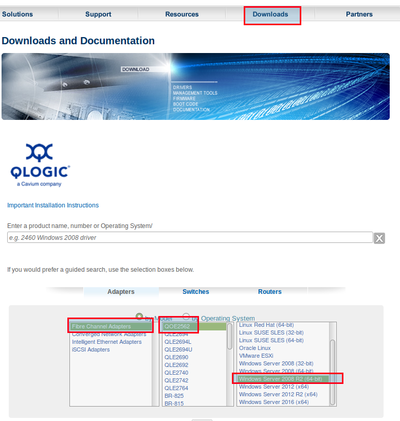
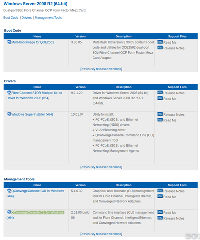
2. Выбрать пакет для загрузки:
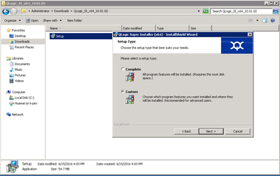
3. Установку пакета выполнять в режиме Custom:
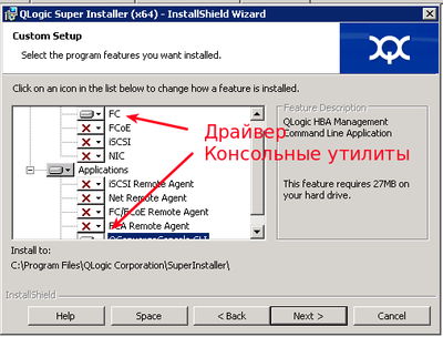
4. Отключить все кроме драйвераFC и консольных утилит QConvergeConsole CLI:
5. Скачать и установить пакет UltraPath for Windows. Ссылку для скачивания последней версии пакета вам должен передать служба технической поддержки.
Сервер подключается к СХД по такой схеме:
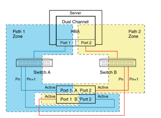
Использовать много-путевой доступ необходимо даже в том случае если на вашем сервере используется 1 порт.
Иначе, например, в случае обновления прошивки на одном из контроллеров СХД произойдет временное отключение вашего сервера от СХД и данные на вашем LUN могу быть повреждены.
Многопутевой ввод-вывод (Multipath I/O) — технология подключения узлов сети хранения данных с использованием нескольких маршрутов. В случае отказа одного из контроллеров, операционная система будет использовать другой для доступа к устройству. Это повышает отказоустойчивость системы и позволяет распределять нагрузку.
Multipath устройства объединяются в одно устройство с помощью специализированного программного обеспечения в новое устройство. Multipath обеспечивает выбор пути и переключение на новый маршрут при отказе текущего. Это происходит невидимо для программ и процессов использующих это устройство. Кроме того Multipath способен распределять передачу данных по разным путям посредством различных алгоритмов, например:
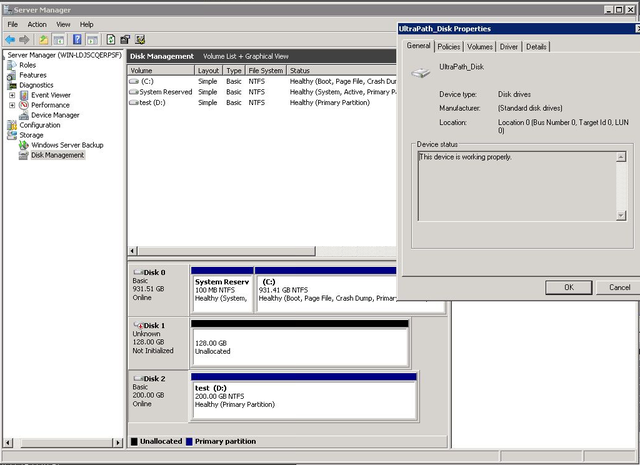
Без Ultrapath ваша система будет видеть 4 устройства вместо одного.
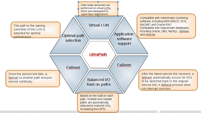
Преимущества Huawei UltraPath
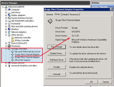
6. После перезагрузки системы в менеджере устройств (Секция Storage Controllers)убедитесь что установлена актуальная версия драйвера Qlogic и Ultra-Path support
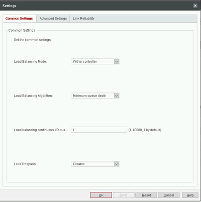
7. Запустить консоль Ultra-Path, зайти в меню System > Global Settings и установить параметры как на этом снимке:
8. Зайдите в менеджер дисков, активируйте диск, создайте раздел с файловой системой.
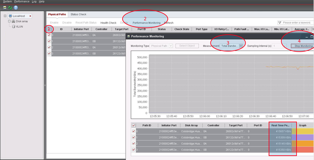
9. В консоли Ultra-Path выберите все пути (1), запустите Performance Monitor (2), выберите тип измерений / measurement (3), запустите мониторинг (4), дайте нагрузку на диск и убедитесь что данные передаются по всем путям.
Содержание
- Подключение Multipath LUN СХД к Windows Server 2008 и Windows Server 2012
- Установка и настройка MPIO в Windows Server 2016/2012R2
- Установка MPIO в Windows Server 2016/2012R2
- Установка MPIO с помощью консоли Server Manager
- Установка MPIO с помощью Powershell
- Настройка MPIO в Windows Server 2016
- SAN Policy
- Подключение СХД Qsan к серверам в среде Windows Server и Hyper-V
- Физическая и логическая коммутация
- Действия на стороне СХД
- Действия на стороне хоста
- Настройка виртуального адаптера Fibre Channel Hyper-V в структуре хранилища VMM
- Перед началом работы
- Развертывание виртуального адаптера Fibre Channel
- Обнаружение и классификация структур Fibre Channel
- Создание виртуальных сетей хранения данных (vSAN) и назначение адаптеров шины
- Создание шаблона виртуальной машины
- Создание зон
- Создание и регистрация LUN
- Создание и развертывание уровня службы
- Дальнейшие действия
- База знаний wiki
- Содержание
- fc подключение к схд сервера под windows
- Задача:
- Решение:
- Многопутевой ввод-вывод (Multipath I/O)
Подключение Multipath LUN СХД к Windows Server 2008 и Windows Server 2012
В предыдущей статье мы рассматривали «Подключение Multipath LUN СХД к VMware ESXi и Debian GNU/Linux». В данной статье продолжаем. Напомню, что используется конфигурация с двумя SAN-свитчами, к каждому из которых, СХД подключена двумя линками.
Подключение Multipath LUN СХД к Windows Server 2012
Multipath Input Output — это система многопутевого подключения блочных устройств. Требуется она для дублирования каналов подключения в целях повышения отказоустойчивости и производительности за счет того, что сервер может обращаться к устройству по нескольким каналам.
Вот так система видит LUN’ы без поддержки MPIO:

Если MPIO по какой-либо причине отключен, требуется включить. Для этого в «панели мониторинга» выбираем меню «управление» и пункт «добавить роли и компоненты».
В «мастере добавления ролей и компонентов» переходим к пункту «компоненты» и выбираем в списке «Multipath I/O», после чего нажимаем виртуальную кнопку «установить».
После этого переходим в систему управления дисковыми массивами в «диспетчере серверов» и через меню «средства» вызываем диалог MPIO:
На вкладке «Обнаружение многопутевых устройств» видим нужные нам LUN’ы и нажимаем кнопку «добавить».
Система предложит перезагрузиться. Соглашаемся. После перезагрузки все LUN’ы доступны как MPIO устройства:
Теперь их требуется подключить к системе, после чего можно создавать тома:
Готово. Теперь созданные тома доступны в системе:
Подключение Multipath LUN СХД к системе Windows Server 2008
Выше мы рассмотрели как подключить LUN к системе Windows Server 2012. В системе Windows Server 2008 процедура несколько отличается.
После загрузки системы, запускаем «Диспетчер сервера»:
В меню «Действие» выбираем пункт «Добавить компоненты»:
В списке активируем переключатель «Многопутевой ввод-вывод» и проходим все этапы установки:
Готово. Теперь нужно активировать распознавание путей. Для этого переходим на «Панель управления» и переключаемся на режим просмотра «Мелкие значки:
Вызываем панель конфигурации „MPIO“:
Где переходим на вкладку „Обнаружение многопутевых устройств“. В списке „Код оборудования“ будут представлены нужные LUN’ы. Нажимаем виртуальную кнопку „Добавить“:
Система предложит перезагрузиться. Соглашаемся:
После перезагрузки в „Диспетчере сервера“ переходим по пунктам „Хранилище“ → „Управление дисками“ и видим LUN’ы как Multipath устройства:
Теперь можно создать тома и подключить к системе:
Готово. Теперь диск доступен в системе. Чтобы убедиться, можно открыть „Мой компьютер“:
Источник
Установка и настройка MPIO в Windows Server 2016/2012R2
В этой статье мы рассмотрим особенности реализации, установки и настройки MPIO в Windows Server 2016/2012 R2. MPIO (Multi—Path Input Output) или многопутевой ввод-вывод, это технология для построения отказоустойчивого транспорта к системе хранения данных (СХД) или выполняющему эти функции серверу за счет использования избыточных путей. Дополнительные пути между сервером и хранилищем создаются с использованием избыточных физических компонентов (коммутаторы, кабели, адаптеры или сетевые карты). Обратная сторона такой избыточности – операционная система может видеть один и тот же LUN по разным путям и считать их разными устройствами.
На следующем скриншоте видно (список подключенных дисков можно вывести с помощью get-disk), что Windows видит без MPIO видит 2 диска по разным путям, которые по факту являются одним LUN:

Если ОС поддерживает MPIO, она будет видеть каждый из презентованных ей дисков в одном экземпляре. При включенном MPIO сервер может обращаться к данным на СХД по нескольким путям, что увеличивает скорость доступа к подключенному LUN и позволяет задействовать для доступа несколько сетевых или HBA-адаптеров.
MPIO может задействовать альтернативный логический путь при выходе из строя одного/нескольких компонентов, заставив операционную систему использовать для доступа к логическому диску (LUN) резервный маршрут, сохраняя непрерывность доступа к данным. Таким образом MPIO является важным компонентом при реализации отказоустойчивой системы доступа к данным, кроме того входящие в состав MPIO модули позволяют распределять нагрузку между различными путями к одному и тому же LUN-у.
Установка MPIO в Windows Server 2016/2012R2
Windows Server поддерживает многопутевой ввод-вывода MPIO начиная с версии Windows Server 2008 R2. Технология Microsoft MPIO позволяет обеспечить высокую доступность и балансировку нагрузки посредством возможности организации нескольких подключений к СХД, не зависит от протоколов и поддерживает подключение дисковых массивов и хранилищ по iSCSI, Fiber Channel и хранилищ SAS.
MPIO-модуль в Windows Server по умолчанию не включен. Установить его в Windows Server 2016 можно двумя способами:
Установка MPIO с помощью консоли Server Manager
Установка MPIO с помощью Powershell
Запустите консоль PowerShell с правами администратора и для установки компонента выполните команду:

Чтобы убедиться, что модуль MPIO установлен в вашем Windows Server, выполните:

Настройка MPIO в Windows Server 2016
После установки MPIO модуля, необходимо активировать его для LUN, которые доступны по нескольким путям. По умолчанию ОС видит каждое подключение к диску как разные логические диски (LUN).
Разрешите модулю DSM от Microsoft (MSDSM) автоматически объединять SAN диски в зависимости от типа подключений. MSDSM автоматически определяет наличие LUN, имеющих несколько путей к СХД и поддерживает большинство популярных систем хранения.
Сделать это можно из командной строки:
Также вы можете включить DSM через графический интерфейс. Откройте консоль управления Server Manager и в меню Tools выберите пункт MPIO (или выполните команду mpiocpl).
Перейдите на вкладку Discover Multi—Paths, включите опцию Add support for SAS devices (или Add support for iSCSI devices, если вы используете iSCSI хранилище) и нажмите Add. После этого перезагрузите сервер.

После перезагрузки откройте диспетчер устройств или диспетчер дисков и убедитесь, что количество подключенных дисков (LUN), доступных серверу уменьшилось в 2 раза (при наличии подключений к СХД по двум путям).
Вы можете управлять списком устройств, для которых включена поддержка MPIO на вкладке MPIO Devices (или командой Get-MSDSMSupportedHw ).

Вы можете добавить новые MPIO устройства, нажав кнопку Add или из PowerShell:
Если вы подключаете iSCSI таргет по 2 путям и хотите использовать MPIO для этого подключения, нужно при подключении Target выбрать iSCSI LUN, нажать кнопку Connect и включить опцию Enable multi—path.

Затем нажмите на кнопку Advanced и привяжите разные IP адреса инициатора к разным IP адресами target.

С помощью PowerShell можно получить текущие настройки MPIO:

Можно изменить настройки MPIO таймеров так (например, установим рекомендованные настройки для flash массива):
Доступны следующие политики балансировки MPIO:
Чтобы задать политику балансировки (например, Round Robin):
Также политику балансировки можно изменить в свойствах подключенного LUN на вкладке MPIO. В этом примере для массива выбрана политика Round Robin.

Чтобы увидеть полный список PowerShell команд, доступных в модуле MPIO, выполните команду:
Get-Command –Module Mpio

SAN Policy
В Windows имеется специальная политика дисков (SAN Policy), которая определяет, нужно ли автоматически монтировать диски при их подключении к хосту.
Текущую настройку SAN Policy можно получить с помощью diskpart. По умолчанию используется SAN политика Offline Shared.
Чтобы автоматически монтировать диски, нужно изменить значение SAN Policy на OnlineAll.
Источник
Подключение СХД Qsan к серверам в среде Windows Server и Hyper-V
Мы продолжаем цикл публикаций из серии How To для пользователей СХД Qsan. В данной статье пойдет речь о подключении СХД к серверам на базе Windows Server, в том числе при использовании функционала виртуализации Hyper-V.
В статье мы будем рассматривать подключения СХД Qsan с использованием блочных протоколов доступа iSCSI и Fibre Channel. Сам процесс подключения можно разделить на несколько основных этапов:
В статье приведены скриншоты настройки операционной системы Windows Server 2016/2019 с нелокализованным интерфейсом. Часть описания, не относящаяся напрямую к ОС, взята из нашего предыдущего обзора по настройке ESXi.
Физическая и логическая коммутация
Совокупность оборудования и линий связи между СХД и серверами образуют так называемую SAN сеть. Отказоустойчивое подключение участников SAN сети подразумевает постоянное наличие хотя бы одного пути между инициатором (хост) и таргетом (СХД). Т.к. СХД сейчас практически поголовно имеют минимум два контроллера, каждый сервер должен иметь связь с каждым из них. В простейшем варианте серверы подключаются к СХД напрямую. Такой режим работы называют Direct Attach. СХД Qsan поддерживают такой режим работы. В этом случае каждый сервер должен иметь двухпортовую HBA для соединения с каждым контроллером СХД. Т.е. между сервером и СХД будет 2 пути. При наличии максимального количества опциональных портов в таком режиме к СХД можно подключить до 10 серверов через iSCSI или до 8 серверов через Fibre Channel.
В большинстве случаев серверы соединяются с СХД через коммутаторы. Для большей надежности их должно быть два (в общем случае их, конечно же, может быть больше, но это они все равно делятся на две группы – фабрики). Этим выполняется защита от выхода из строя самого коммутатора, линка и порта контроллера СХД/HBA. В этом случае каждый сервер и каждый контроллер СХД подключается к каждому коммутатору. Т.е. между каждым сервером и СХД будет 4 пути (в случае двух коммутаторов).
Для Qsan параметр MTU меняется на каждом порту каждого контроллера в меню iSCSI Ports
В Windows Server параметр MTU меняется в настройках драйвера адаптера:
Control PanelNetwork and InternetNetwork Connections → Свойства конкретного адаптера → Configure → Advanced → Jumbo Packet (у некоторых адаптеров этот пункт может называться что-то типа Large Packets)
Для получения инструкций по изменению MTU у физических коммутаторов рекомендуем обратиться к документации конкретного производителя.
Действия на стороне СХД
Необходимые настройки на СХД можно разделить на два этапа:
Настраивать интерфейсы требуется в основном в случае использования протокола iSCSI: необходимо задать IP адреса портов на вкладке iSCSI Ports. IP адреса портов должны быть из разных подсетей, чтобы однозначно маршрутизировался трафик на стороне хоста.
В случае использования интерфейса Fibre Channel ничего настраивать, как правило, не нужно.
Далее необходимо создать пространство хранения. Сначала создается пул – группа физических накопителей, работающих совместно. Пулов в пределах СХД может быть несколько. Накопители внутри пула объединяются в соответствии с выбранным при его создании уровнем RAID, обеспечивая заданную надежность. Пулы создаются на вкладке Pools → Create Pool, где запускается пошаговый мастер.
Помимо обычных пулов Qsan поддерживает создание AutoTiering пулов при условии активации соответствующей лицензии. С принципом работы таких пулов можно ознакомиться в отдельной статье.
После создания пула(ов) необходимо создать тома (volume): Volumes → Create volumes. Также запустится пошаговый мастер создания тома.
Необходимо задать требуемый размер тома, тип тома выбирается как RAID volume. Рассмотрим их более подробно.
Заключительным этапом в настройке СХД является публикация томов для доступа к ним со стороны хостов через функционал LUN mapping → Map LUN.
Действия на стороне хоста
Первоначально необходимо один раз установить на сервере компонент Multipath IO, который обеспечивает работу многопутевого ввода/вывода. Данное действие производится через стандартный диалог Add Roles and Features
При использовании протокола iSCSI необходимо выполнить:
При использовании протокола Fibre Channel все гораздо проще: достаточно выполнить Rescan для обнаружения нового тома. В нашем примере это том с LUN доступный по 4 путям. Как и в случае с iSCSI следует убедиться, что для диска установлена политика Round Robin, при которой все доступные пути до СХД будут использоваться равномерно.
Важное замечание касательно конфигурирования MPIO. По умолчанию Windows видит дисковые устройства по отдельности, т.е. каждый путь к устройству – это отдельный диск.
Чтобы ОС «склеила» все одинаковые диски в единое устройство, необходимо в стандартной оснастке MPIO добавить новое устройство как многопутевое. Для iSCSI устройств устанавливается отдельное разрешение. По окончании настройки потребуется перезагрузить сервер. Данную настройку необходимо произвести однократно для каждой СХД. После чего все вновь презентованные диски будут опознаваться ОС как многопутевые.
В случае использования кластера из нескольких хостов Windows Server, действия, описанные выше, необходимо повторить на каждом из хостов. После чего диски, появившиеся в системе, можно добавлять в дисковые ресурсы кластера.
В рамках этой статьи были рассмотрены преимущественно базовые операции, необходимые для подключения серверов Windows Server к СХД Qsan. Для получения более полной информации настоятельно рекомендуется ознакомиться с руководствами пользователей, предоставляемыми обоими вендорами.
Источник
Настройка виртуального адаптера Fibre Channel Hyper-V в структуре хранилища VMM
Поддержка этой версии Virtual Machine Manager (VMM) прекращена. Рекомендуем перейти на VMM 2019.
В этой статье описывается настройка виртуального адаптера Fibre Channel Hyper-V в структуре хранилища System Center Virtual Machine Manager (VMM).
Виртуальный адаптер Fibre Channel позволяет виртуальным машинам Hyper-V напрямую подключаться к хранилищу на основе Fibre Channel. Hyper-V предоставляет порты Fibre Channel в операционных системах на виртуальных машинах, что позволяет виртуализировать приложения и рабочие нагрузки, которые имеют зависимости от хранилища Fibre Channel. Кроме того, можно кластеризовать операционные системы на виртуальных машинах по Fibre Channel.
Перед началом работы
Вам потребуется следующее.
Развертывание виртуального адаптера Fibre Channel
Необходимо сделать следующее:
Обнаружение и классификация структур Fibre Channel
Создание виртуальных сетей хранения данных (vSAN) и назначение адаптеров шины
Вы можете создать виртуальные сети хранения данных и назначить для них адаптеры шины. На каждом узле может быть создана одна или несколько виртуальных сетей хранения данных. Каждая виртуальная сеть хранения данных может содержать только адаптеры шины, принадлежащие одной и той же структуре.
Виртуальные адаптеры шины, представляющие виртуализацию адаптеров шины Fibre Channel, используются виртуальными машинами для подключения к виртуальным сетям хранения данных. Каждый виртуальный адаптер шины имеет имя узла в Интернете (WWNN), отличающееся от WWNN адаптера шины узла. С помощью NPIV адаптер шины главного компьютера можно сопоставить с несколькими виртуальными адаптерами шины. Порты адаптеров шины, назначенные виртуальной сети хранения данных, при необходимости могут добавляться или удаляться.
Создание шаблона виртуальной машины
Виртуальные адаптеры шины используются виртуальными машинами для подключения к виртуальным сетям хранения данных. Чтобы подключить виртуальные адаптеры шины к виртуальным сетям хранения данных, сначала необходимо их добавить в профиль оборудования шаблона виртуальной машины.
После развертывания виртуальной машины в узле можно соотнести зоны массива хранения данных виртуального адаптера Fibre Channel с виртуальной машиной. Затем необходимо создать LUN и зарегистрировать его (снять маску) на виртуальной машине.
Создание зон
Зоны используются для подключения массива Fibre Channel к узлу или виртуальной машине. Целевые порты массива хранения данных сопоставляются с портами адаптеры шины на узле или портами виртуального адаптера шины на виртуальной машине. Вы можете создать зоны для узла, виртуальной машины или их обоих. Для отказоустойчивых кластеров Hyper-V зона необходима для каждого узла в кластере. Обратите внимание на следующее.
Настройте зоны следующим образом.
Создание и регистрация LUN
Для доступа к ресурсам массивов хранения данных узла, виртуальной машины или уровня службы узла на них должны быть созданы и зарегистрированы (сняты маски) номера LUN.
Создание и развертывание уровня службы
Дальнейшие действия
Настройте хранилище для узлов и кластеров Hyper-V.
Источник
База знаний wiki
Продукты
Статьи
Содержание
fc подключение к схд сервера под windows
Задача:
Как подключиться к LUN выделенному на системе хранения
Решение:
Обновите операционную систему, скачайте с сайта, извлеките из архива, установите пакет QConvergeConsole CLI for Windows и пакет UltraPath for Windows.

2. Выбрать пакет для загрузки:

3. Установку пакета выполнять в режиме Custom:

4. Отключить все кроме драйвераFC и консольных утилит QConvergeConsole CLI:

5. Скачать и установить пакет UltraPath for Windows. Ссылку для скачивания последней версии пакета вам должен передать служба технической поддержки.
Сервер подключается к СХД по такой схеме:

Многопутевой ввод-вывод (Multipath I/O)
Использовать много-путевой доступ необходимо даже в том случае если на вашем сервере используется 1 порт.
Иначе, например, в случае обновления прошивки на одном из контроллеров СХД произойдет временное отключение вашего сервера от СХД и данные на вашем LUN могу быть повреждены.
Многопутевой ввод-вывод (Multipath I/O) — технология подключения узлов сети хранения данных с использованием нескольких маршрутов. В случае отказа одного из контроллеров, операционная система будет использовать другой для доступа к устройству. Это повышает отказоустойчивость системы и позволяет распределять нагрузку.
Multipath устройства объединяются в одно устройство с помощью специализированного программного обеспечения в новое устройство. Multipath обеспечивает выбор пути и переключение на новый маршрут при отказе текущего. Это происходит невидимо для программ и процессов использующих это устройство. Кроме того Multipath способен распределять передачу данных по разным путям посредством различных алгоритмов, например:
Без Ultrapath ваша система будет видеть 4 устройства вместо одного.
Преимущества Huawei UltraPath

6. После перезагрузки системы в менеджере устройств (Секция Storage Controllers)убедитесь что установлена актуальная версия драйвера Qlogic и Ultra-Path support

7. Запустить консоль Ultra-Path, зайти в меню System > Global Settings и установить параметры как на этом снимке:

8. Зайдите в менеджер дисков, активируйте диск, создайте раздел с файловой системой.

9. В консоли Ultra-Path выберите все пути (1), запустите Performance Monitor (2), выберите тип измерений / measurement (3), запустите мониторинг (4), дайте нагрузку на диск и убедитесь что данные передаются по всем путям.
Источник
 Loading…
![]()
SANsurfer FC HBA CLI
User’s Guide
Command Line Interface for QLogic Fibre Channel Host Bus Adapters

SANsurfer FC HBA CLI User’s Guide
Command Line Interface for QLogic Fibre Channel Host Bus Adapters
S
Information furnished in this manual is believed to be accurate and reliable. However, QLogic Corporation assumes no responsibility for its use, nor for any infringements of patents or other rights of third parties which may result from its use. QLogic Corporation reserves the right to change product specifications at any time without notice. Applications described in this document for any of these products are for illustrative purposes only. QLogic Corporation makes no representation nor warranty that such applications are suitable for the specified use without further testing or modification. QLogic Corporation assumes no responsibility for any errors that may appear in this document.
Apple, Finder, Mac OS, Macintosh, and Power Mac registered trademarks, and Safari is a trademark of Apple, Inc., registered in the U.S. and other countries.
EMC is a registered trademark of EMC Corporation.
Intel and Pentium are trademarks of Intel Corporation in the U.S. and other countries. Linux is a registered trademark of Linus Torvalds.
Microsoft, Windows, Windows NT operating system, Windows 2000 operating system, Windows Server 2003 operating system, Windows XP Professional operating system, and Windows Vista operating system are registered trademarks of Microsoft Corporation in the United States and other countries.
Novell and NetWare are registered trademarks of Novell, Inc.
IBM and PowerPC are registered trademarks of International Business Machines Corporation in the United States, other countries, or both.
QLogic, the QLogic logo, QLA, and SANsurfer are registered trademarks of QLogic Corporation. Red Hat and all Red Hat-based are trademarks or registered trademarks of Red Hat, Inc.
Solaris is a registered trademark of Sun Microsystems, Inc., in the United States and other countries
SPARC is a registered trademark of SPARC International, Inc. Products bearing SPARC trademarks are based on an architecture developed by Sun Microsystems, Inc.
StuffIt is a registered trademark of Smith Micro Software, Inc. SuSE is a registered trademark of SuSE Linux AG.
VMware is a registered trademark of VMware, Inc. in the United States and/or other jurisdictions.
All other brand and product names are trademarks or registered trademarks of their respective owners.
Document Revision History
Revision A, August 20, 2004
Revision B, September 28, 2005
Revision C, June 7, 2006
Revision D, October 1, 2006
Revision E, February 1, 2007
Revision F, February 2008
|
Changes |
Sections Affected |
|
Revision F Changes: |
|
|
Changed NVRAM to HBA Parameters. |
All |
|
Changed Option ROM to Flash. |
All |
© 2004–2008 QLogic Corporation. All Rights Reserved Worldwide.
First Published: March 2004
QLogic Corporation, 26650 Aliso Viejo Parkway, Aliso Viejo, CA 92656, (800) 662-4471 or (949) 389-6000

A
SANsurfer FC HBA CLI User’s Guide Command Line Interface for QLogic Fibre Channel Host Bus Adapters
|
Changed HBA No. to HBA Instance. |
All |
||
|
Changed SFF DMI to HBA transceiver details. |
All |
||
|
Updated supported QLogic HBA list. |
Section 1.3 |
||
|
Updated supported operating system list. |
Section 1.4 |
||
|
All non-interactive information moved from |
Section 4, Section 5 |
||
|
Section 4 to Section 5. |
|||
|
Command line options put in alphabetical order. |
Table 2-1, Section 4 |
||
|
Added Appendix B: XML Format 2. |
Appendix B |
||
|
Added port virtualization (NPIV) information. |
Section 4.14, Section 5.3.33 |
||
|
Added support for Red Hat Linux REL 5.1. |
Section 3.2.2 |
||
|
Removed installation/uninstallation instructions for |
Section 3.2.3 |
||
|
Solaris SPARC 6 and 7. |
|||
|
Added NPIV information. |
Section 4.14.1 |
||
|
Added OS LUN Name (Solaris and Linux). |
Section 4.4 |
||
|
Added guide overview section, including a descrip- |
Section 1.2 |
||
|
tion of what’s in the guide and documentation con- |
|||
|
ventions used. |
|||
|
Added interactive mode exit codes listing. |
Appendix C |
||
|
Moved tables other than help commands from |
Section 4 |
||
|
Help Commands appendix to appropriate interac- |
|||
|
tive commands sections. |
|||
|
Expanded iiDMA settings information. |
Section 4.5 |
||
|
Added Virtual Menu information. |
Section 4.14 |
||
|
Expanded HBA parameter templates information. |
Section 4.10.5 |
||
|
Expanded diagnostic testing information. |
Section 4.12 |
||
|
Revision E Changes: |
|||
|
Expanded product description. |
Section 1.1 |
||
|
Split supported HBAs and operating systems into |
Section 1.3, Section 1.4 |
||
|
two sections. Updated list of supported operating |
|||
|
systems. |
|||
|
Added system requirements section. |
Section 1.5 |
||

SANsurfer FC HBA CLI User’s Guide
Command Line Interface for QLogic Fibre Channel Host Bus Adapters
S
Changed bullets describing interactive and non-interactive modes.
Clarified the note about starting SANsurfer FC HBA CLI on a Solaris console serial port.
Added Macintosh column to Table 2-1.
Added support for Linux IOCTL module driver and driver on the OS installation CD (inbox driver).
Split Windows command line installation into two sections (standard and silent). Changed installation instructions. Added new parameters to command line for silent installation.
Split Solaris installation and uninstallation into three sections:
Solaris SPARC 6 and 7
Solaris SPARC 8, 9, 10 Solaris x86 8, 9, 10
Added Mac OS X command line installation instructions.
In Windows uninstall (standard), added how to invoke the exe package and remove the installed features.
In Windows uninstall (command line), changed the uninstall directions.
Added Mac OS X instructions to manually uninstall the package.
Replaced node name, port name, WWPN, and WWNN with variables (xx) in screen shots for security purposes.
Added a note to Display LUN List and Selective LUNs sections defining the maximum number of LUNs supported by the Solaris QLA and QLC drivers.
Added text to the Target Persistent Binding section defining the number of targets and the range of target IDs for Solaris, which is based in the HBA type.
Changed Boot Device Selection to Boot Device
Settings.
Section 2.2, Section 2.3
Section 2.2
Section 2.3
Section 3, Section 4, Section 5
Section 3.2.1.2
(These Solaris versions no longer supported.) Section 3.2.3.1, Section 3.3.3.1
Section 3.2.3.2, Section 3.3.3.2
Section 3.2.4.2
Section 3.3.1.1
Section 3.3.1.2
Section 3.3.4
Section 4
Section 4.7
Section 4.6, Section 4.6.2
Section 4.8

A
SANsurfer FC HBA CLI User’s Guide Command Line Interface for QLogic Fibre Channel Host Bus Adapters
|
Expanded Save/Update Flash section to list which |
Section 4.10 |
||
|
OSs and HBAs save/update flash, BIOS, or the |
|||
|
option ROM image. |
|||
|
Added description and preparation instructions for |
Section 4.12.1.1, Section 4.12.2 |
||
|
loopback and read/write buffer tests. Added |
|||
|
description of these test results. |
|||
The following options and commands were added in Rev. E:
|
Host Topology (command line option -tp) |
Section 4.1.2, Section 5.3.31 |
|
|
HBA Alias (command line option -ha) |
Section 4.2.1.2, Section 5.3.14 |
|
|
HBA Port Alias (command line option -pa) |
Section 4.2.1.3, Section 5.3.25 |
|
|
SFF DMI (command line option -dm) |
Section 4.12, Section 5.3.5 |
|
|
The following options and commands were changed in Rev. E: |
||
|
Host Information (command line option -g): |
Section 4.2.1 |
|
|
removed QLogic direct driver version from the list |
||
|
of displayed information. |
||
|
For Host Configuration (command line option -z), |
Section 4.2 |
|
|
made the following changes to the list of displayed |
||
|
information: |
||
|
Added VPD information to display HBA information |
||
|
(command line option -I). |
||
|
Added view driver settings (command line option |
||
|
-fg). |
||
|
Removed run loopback test (command line option |
||
|
-kl). |
||
|
Removed run read/write test (command line option |
||
|
-kr). |
||
|
Removed display and change HBA statistics (com- |
||
|
mand line option -gs). |
||
|
Removed display and change link status (com- |
||
|
mand line option -ls). |
||
|
Also changed the list order to reflect the order in |
||
|
which the commands are displayed. |
||
|
Show HBA Information (command line option -i): |
Section 4.2, Section 4.3.1 |
|
|
Added HBA Alias and Port Alias to list of shown |
||
|
information. |
||
|
Changed PCI bus number to PCI device number. |
||
|
Show Device List (command line option -t): added |
4.5, 4.4.1 |
|
|
Serial Number to the list of displayed information. |
||
SANsurfer FC HBA CLI User’s Guide
Command Line Interface for QLogic Fibre Channel Host Bus Adapters
S
|
Configure HBA Settings (-n): added option to |
4.7.1, Section 5.3.22 |
|
|
restore the BIOS (QLA/QLE/QEM24xx HBAs). |
||
|
Selective LUNs (command line option -m): added |
4.8.1.2, Section 5.3.21 |
|
|
ALL option to command line to view all selective |
||
|
LUNs for all HBA ports. |
||
|
Set Boot Device (-e): removed references to OSs |
4.9.2.1.1 |
|
|
from the third paragraph; this command now |
||
|
applies to all OSs. |
||
|
Diagnostics (command line options -kl and -dr): |
4.17.1.2.1, 5.3.17 |
|
|
DataPattern (DP) parameter: added CRPAT, |
||
|
CSPAT, and CJTPAT. |
4.17.1.2.2, Table 5-5 |
|
|
DataSize (DS) parameter: added 128-byte value |
||
|
for read/write buffer test. Added 128, 256, 512, |
||
|
1024, 2048, 4096, 8192, 16384, 32768, 65535 |
||
|
byte values for loopback test. Added default val- |
||
|
ues. |
4.17.1.2.3, Table 5-5 |
|
|
TestCount (TC) parameter: changed the number of |
||
|
loopback tests that can be run from 0–10000 to |
||
|
0–65535. |
||
|
TestIncrement (TI) parameter: increased test incre- |
4.17.1.2.4, Table 5-5 |
|
|
ment for the loopback test from 1–10000 to |
||
|
1–65535. |
||
|
Output in XML Format (command line option -x): |
Section 5.3.34 |
|
|
Added XML format for HBA alias (command line |
Section 5.3.14 |
|
|
option -ha). |
Section 5.3.25 |
|
|
Added XML format for HBA port alias (command |
||
|
line option -pa). |
Section 5.3.5 |
|
|
Added XML format for SFF DMI (command line |
||
|
option -dm). |
Section 5.3.31 |
|
|
Added XML format for host topology (command |
||
|
line option -tp). |
||
|
Target Persistent Binding (command line option |
Section 5.3.24 |
|
|
-p): added ALL parameter to show target persistent |
||
|
binding information for all HBA ports. |
||

A
SANsurfer FC HBA CLI User’s Guide Command Line Interface for QLogic Fibre Channel Host Bus Adapters
|
Revision D Changes: |
|||
|
Operating systems supported: |
All |
||
|
Windows 2003 Server™ and Enterprise Server: |
|||
|
added x64; removed IEM64T and AMD64. Added |
|||
|
Windows® XP. |
|||
|
Red Hat™ Linux® AS: added x86_64; removed |
|||
|
IEM64T and AMD64. |
|||
|
SuSE® Linux Enterprise Server (SLES) 8 and 9: |
|||
|
added x86_64; removed IEM64T and AMD64. |
|||
|
Removed Power PC (PPC) SLES 8 and 9. |
|||
|
Solaris® SPARC®: removed v2.7; added version 7. |
|||
|
Solaris: removed 9 x86 and 10 x86; added x86, |
|||
|
v2.9, 10. |
|||
|
Removed the sentence “SANsurfer FC HBA CLI |
Section 1 |
||
|
does not provide any features that require a GUI.” |
|||
|
Added QEM2462 and QLA/QLE2xx to list of sup- |
Section 1 |
||
|
ported HBAs. |
|||
|
Changed standard (GUI) install instructions for |
3.1.1.1 |
||
|
Windows operating systems. |
|||
|
Changed package name version to xx, which indi- |
3.1.1.2, 3.1.3.1, 3.12.3.3 |
||
|
cates the current version of SANsurfer FC HBA |
|||
|
CLI. |
|||
|
Changed step 1 of the Mac OX installation proce- |
3.1.4 |
||
|
dure. Removed the steps to create the root user, |
|||
|
log out of the current user account, and log into the |
|||
|
root user (previously steps 2, 3, 4). |
|||
|
Changed WWPN in example text to generic xx for |
Section 4 |
||
|
consistency. |
|||
|
Changed name of Show System Information sub- |
4.2.1, 4.2.2, 4.2.4, 4.2.5 |
||
|
menus. |
|||
|
Changed name of Boot Device to Boot Device |
4.10 |
||
|
Selection in interactive mode. |
|||
|
HBA Parameters (Table 4-2, Table 6-12): |
4.6.1.2, Table 5-9 |
||
|
Changed value of ResetDelay, ExecutionThrottle, |
|||
|
and LinkDownTimeOut parameters. Added |
|||
|
(QLA/QLE23xx HBAs) quantifier to EnableEx- |
|||
|
tended Logging and EnableLIPFullLogin parame- |
|||
|
ters. |
|||
|
Added a list of valid data patterns for the DataPat- |
4.17.1.2.1, Table 5-6 |
||
|
tern diagnostic parameter (Table 4-4, Table 5-6). |
|||

SANsurfer FC HBA CLI User’s Guide
Command Line Interface for QLogic Fibre Channel Host Bus Adapters
S
The following options and commands were changed in Rev. D:
|
Interactive mode commands: Changed instructions |
||
|
and the example text to new port sorting and num- |
||
|
bering scheme. No change to command function. |
||
|
Non-interactive mode commands: Changed the |
||
|
HBA Port No. parameter to HBA No. parameter |
||
|
to support new port sorting and numbering |
||
|
scheme. No change to command function. |
||
|
Display HBA Settings (-c) |
4.3, 5.3.3 |
|
|
DisplayHBA Information (-i) |
4.4, 5.3.1 |
|
|
Display Device List (-t) |
5 4.5, 5 |
|
|
Display LUN List (-l) |
4.6, 5 |
|
|
Configure HBA Settings (-n) |
4.7, 5 |
|
|
Target Persistent Binding (-p) |
4.8, 5 |
|
|
Selective LUNs (-m) |
4.9, 5 |
|
|
Boot Device Selection (-e) |
4.10, 5 |
|
|
Driver Settings (-fs) |
4.11, 5 |
|
|
View Driver Settings (-fg) |
4.12, 5 |
|
|
Save/Update Flash (-b) |
4.12, 5 |
|
|
Save/Update NVRAM (-r) |
4.11, 5 |
|
|
Flash HBA Beacon (-a and -tb) |
4.16, 5 |
|
|
Diagnostics (-kl and -kr) |
4.17, 5 |
|
|
Statistics (-gs and -ls) |
4.18, 5 |
|
|
Host Information (-g): |
4.2.1, 4.2.4 |
|
|
Quantified that the direct driver version is only |
||
|
displayed in Windows. No longer shows firm- |
||
|
ware version. Shows new HBA number (HBA 0–n) |
||
|
Display HBA Information (-I). |
4.4, 5.4.8 |
|
|
The following new general information shows: |
||
|
HBA instance, HBA ID, OptionROM BIOS version, |
||
|
OptionROM FCode version, OptionROM EFI ver- |
||
|
sion, OptionROM firmware version, total number of |
||
|
devices. |
||
|
The following general information has been |
||
|
removed: |
Device target count |
|
|
The following VPD information has been removed: |
||
|
Asset tag |
End tag |
|

A
SANsurfer FC HBA CLI User’s Guide Command Line Interface for QLogic Fibre Channel Host Bus Adapters
|
Display LUN List (-l): |
4.6 |
|||
|
In interactive mode, added target type to infor- |
||||
|
mation displayed. |
||||
|
Removed asset tag and end tag from list of |
||||
|
VPD information. |
||||
|
In example text, changed the first two option |
||||
|
names of the Selective LUN(s) Display Configura- |
||||
|
tion menu. |
||||
|
In example text, changed the first two option |
||||
|
names of the Selective LUN(s) Configuration — |
||||
|
HBA/Device menu. |
||||
|
Boot Device Selection (-eE): In interactive mode, |
4.10, 5.3.6 |
|||
|
added new HBA Boot Device menu to example |
||||
|
text. |
||||
|
Target Persistent Binding (-p): |
4.8, 5.9 |
|||
|
In interactive mode, changed first two option |
||||
|
names of Target Persistent Binding menu in the |
||||
|
example text. |
||||
|
Driver Settings (-fs): Changed from bind By |
4.11 |
|||
|
WWPN to bind by Port ID. |
||||
|
Save/Update Flash (-b): |
4.12, 5.3.2 |
|||
|
In interactive mode, removed secondary subti- |
||||
|
tles of Option ROM Update menu in the example |
||||
|
text. |
||||
|
In non-interactive mode, added new all |
||||
|
parameter following the boot parameter. |
||||
|
Save/Update NVRAM (-r): In interactive mode, |
4.11 |
|||
|
removed the secondary subtitles of the NVRAM |
||||
|
Update Menu in the example text. |
||||

SANsurfer FC HBA CLI User’s Guide
Command Line Interface for QLogic Fibre Channel Host Bus Adapters
Notes
S
![]()
Table of Contents
|
Section 1 |
Introduction |
||
|
1.1 |
Product Overview . . . . . . . . . . . . . . . . . . . . . . . . . . . . . . . . . . . . . . . . . . . . . |
1-1 |
|
|
1.2 |
Guide Overview . . . . . . . . . . . . . . . . . . . . . . . . . . . . . . . . . . . . . . . . . . . . . . |
1-1 |
|
|
1.2.1 |
How this Guide is Organized. . . . . . . . . . . . . . . . . . . . . . . . . . . . . . . . |
1-1 |
|
|
1.2.2 |
Documentation Conventions . . . . . . . . . . . . . . . . . . . . . . . . . . . . . . . . |
1-2 |
|
|
1.3 |
Supported QLogic HBAs . . . . . . . . . . . . . . . . . . . . . . . . . . . . . . . . . . . . . . . |
1-4 |
|
|
1.4 |
Supported Operating Systems . . . . . . . . . . . . . . . . . . . . . . . . . . . . . . . . . . . |
1-4 |
|
|
1.5 |
System Requirements . . . . . . . . . . . . . . . . . . . . . . . . . . . . . . . . . . . . . . . . . |
1-5 |
|
|
1.5.1 |
Hardware Requirements . . . . . . . . . . . . . . . . . . . . . . . . . . . . . . . . . . . |
1-5 |
|
|
1.5.2 |
Software Requirements . . . . . . . . . . . . . . . . . . . . . . . . . . . . . . . . . . . . |
1-6 |
|
|
1.5.2.1 |
Unsupported Features . . . . . . . . . . . . . . . . . . . . . . . . . . . . . . . . |
1-6 |
|
|
1.6 |
Technical Support. . . . . . . . . . . . . . . . . . . . . . . . . . . . . . . . . . . . . . . . . . . . . |
1-7 |
|
|
1.6.1 |
Availability . . . . . . . . . . . . . . . . . . . . . . . . . . . . . . . . . . . . . . . . . . . . . . |
1-8 |
|
|
1.6.2 |
Training . . . . . . . . . . . . . . . . . . . . . . . . . . . . . . . . . . . . . . . . . . . . . . . . |
1-8 |
|
|
1.7 |
Contact Information . . . . . . . . . . . . . . . . . . . . . . . . . . . . . . . . . . . . . . . . . . . |
1-8 |
|
Section 2 |
Getting Started |
|
|
2.1 |
Introduction. . . . . . . . . . . . . . . . . . . . . . . . . . . . . . . . . . . . . . . . . . . . . . . . . . |
2-1 |
|
2.2 |
Starting Interactive Mode . . . . . . . . . . . . . . . . . . . . . . . . . . . . . . . . . . . . . . . |
2-1 |
|
2.3 |
Starting Non-interactive Mode . . . . . . . . . . . . . . . . . . . . . . . . . . . . . . . . . . . |
2-3 |
|
2.4 |
Terminology . . . . . . . . . . . . . . . . . . . . . . . . . . . . . . . . . . . . . . . . . . . . . . . . . |
2-6 |
|
Section 3 |
Initial Installation |
||
|
3.1 |
Downloading the Installation Package . . . . . . . . . . . . . . . . . . . . . . . . . . . . . |
3-1 |
|
|
3.2 |
Installing SANsurfer FC HBA CLI. . . . . . . . . . . . . . . . . . . . . . . . . . . . . . . . . |
3-2 |
|
|
3.2.1 |
Windows Installation . . . . . . . . . . . . . . . . . . . . . . . . . . . . . . . . . . . . . . |
3-2 |
|
|
3.2.1.1 |
Standard (GUI) Installation . . . . . . . . . . . . . . . . . . . . . . . . . . . . . |
3-2 |
|
|
3.2.1.2 |
Command Line Installation . . . . . . . . . . . . . . . . . . . . . . . . . . . . . |
3-5 |
|
|
3.2.2 |
Linux Installation . . . . . . . . . . . . . . . . . . . . . . . . . . . . . . . . . . . . . . . . . |
3-7 |
|
|
3.2.3 |
Solaris Installation . . . . . . . . . . . . . . . . . . . . . . . . . . . . . . . . . . . . . . . . |
3-8 |
|
|
3.2.3.1 |
Solaris SPARC 8, 9, 10 Installation . . . . . . . . . . . . . . . . . . . . . . |
3-8 |
|
|
3.2.3.2 |
Solaris x86 9 and 10 Installation. . . . . . . . . . . . . . . . . . . . . . . . . |
3-9 |
|
|
3.2.4 |
Macintosh Installation . . . . . . . . . . . . . . . . . . . . . . . . . . . . . . . . . . . . . |
3-11 |
|
|
3.2.4.1 |
Standard (GUI) Installation . . . . . . . . . . . . . . . . . . . . . . . . . . . . . |
3-11 |
|
|
3.2.4.2 |
Command Line Installation . . . . . . . . . . . . . . . . . . . . . . . . . . . . . |
3-11 |

SANsurfer FC HBA CLI User’s Guide
Command Line Interface for QLogic Fibre Channel Host Bus Adapters
S
|
3.3 |
. . . . . . . . . . . . . . . . . . . . . . . . . . . . . .Uninstalling SANsurfer FC HBA CLI |
3-12 |
||
|
3.3.1 |
Windows Uninstall . . . . . . . . . . . . . . . . . . . . . . . . . . . . . . . . . . . . . . . . |
3-13 |
||
|
3.3.1.1 |
Standard (GUI) Uninstall. . . . . . . . . . . . . . . . . . . . . . . . . . . . . . . |
3-13 |
||
|
3.3.1.2 |
Command Line Uninstall. . . . . . . . . . . . . . . . . . . . . . . . . . . . . . . |
3-13 |
||
|
3.3.2 |
Linux Uninstall . . . . . . . . . . . . . . . . . . . . . . . . . . . . . . . . . . . . . . . . . . . |
3-13 |
||
|
3.3.3 |
Solaris Uninstall. . . . . . . . . . . . . . . . . . . . . . . . . . . . . . . . . . . . . . . . . . |
3-13 |
||
|
3.3.3.1 |
Solaris SPARC 8, 9, and 10 Uninstall. . . . . . . . . . . . . . . . . . . . . |
3-14 |
||
|
3.3.3.2 |
Solaris x86 8, 9, and 10 Uninstall . . . . . . . . . . . . . . . . . . . . . . . . |
3-14 |
||
|
3.3.4 |
Macintosh Uninstall . . . . . . . . . . . . . . . . . . . . . . . . . . . . . . . . . . . . . . . |
3-15 |
|
Section 4 |
Interactive Commands |
||
|
4.1 |
General Information Menu (Command Line Option -g) . . . . . . . . . . . . . . . . |
4-2 |
|
|
4.1.1 |
Host Information (Command Line Option -g). . . . . . . . . . . . . . . . . . . . |
4-2 |
|
|
4.1.2 |
Host Topology (Command Line Option -tp | -topology) . . . . . . . . . . . . |
4-3 |
|
|
4.1.2.1 |
Display (Host Topology) (Command Line Option -tp | |
||
|
-topology) . . . . . . . . . . . . . . . . . . . . . . . . . . . . . . . . . . . . . . . . . . |
4-4 |
||
|
4.1.2.2 |
Save As Txt File (Command Line Option -b) . . . . . . . . . . . . . . . |
4-8 |
|
|
4.1.2.3 |
Save As XML File . . . . . . . . . . . . . . . . . . . . . . . . . . . . . . . . . . . . |
4-8 |
|
|
4.1.3 |
Generate Report (Command Line Option -z) . . . . . . . . . . . . . . . . . . . |
4-9 |
|
|
4.1.3.1 |
Generate Report (Per HBA Port) . . . . . . . . . . . . . . . . . . . . . . . . |
4-9 |
|
|
4.1.3.2 |
Generate Report (All HBAs) (Command Line Option -z) . . . . . . |
4-17 |
|
|
4.1.4 |
Refresh . . . . . . . . . . . . . . . . . . . . . . . . . . . . . . . . . . . . . . . . . . . . . . . . |
4-17 |
|
|
4.2 |
HBA Information Menu (Command Line Option -i) . . . . . . . . . . . . . . . . . . . |
4-17 |
|
|
4.2.1 |
HBA General Information (per HBA Port) . . . . . . . . . . . . . . . . . . . . . . |
4-18 |
|
|
4.2.1.1 |
HBA Information (Command Line Option -i). . . . . . . . . . . . . . . . |
4-18 |
|
|
4.2.1.2 |
HBA Alias (Command Line Option -ha) . . . . . . . . . . . . . . . . . . . |
4-18 |
|
|
4.2.1.3 |
HBA Port Alias (Command Line Option -pa) . . . . . . . . . . . . . . . |
4-19 |
|
|
4.2.1.4 |
HBA VPD Information (Command Line Option -l and |
||
|
Reserved Word “vpd”) . . . . . . . . . . . . . . . . . . . . . . . . . . . . . . . . |
4-20 |
||
|
4.2.2 |
HBA Information (All HBAs). . . . . . . . . . . . . . . . . . . . . . . . . . . . . . . . . |
4-21 |
|
|
4.2.2.1 |
Information . . . . . . . . . . . . . . . . . . . . . . . . . . . . . . . . . . . . . . . . . |
4-21 |
|
|
4.3 |
HBA Parameters Menu . . . . . . . . . . . . . . . . . . . . . . . . . . . . . . . . . . . . . . . . |
4-21 |
|
|
4.3.1 |
HBA Parameters (Per HBA Port). . . . . . . . . . . . . . . . . . . . . . . . . . . . . |
4-22 |
|
|
4.3.1.1 |
Display HBA Parameters (Command Line Option -c#). . . . . . . . |
4-22 |
|
|
4.3.1.2 |
Configure HBA Parameters (Command Line Option -n). . . . . . . |
4-23 |
|
|
4.3.1.3 |
Restore Defaults . . . . . . . . . . . . . . . . . . . . . . . . . . . . . . . . . . . . . |
4-29 |
|
|
4.3.2 |
HBA Parameters (All HBAs) . . . . . . . . . . . . . . . . . . . . . . . . . . . . . . . . |
4-29 |

A
SANsurfer FC HBA CLI User’s Guide Command Line Interface for QLogic Fibre Channel Host Bus Adapters
|
4.4 |
. . . . . . . . . . . . . .Target/LUN List Menu (Command Line Options -t and -l) |
4-30 |
||
|
4.4.1 |
Target/LUN List (Per HBA Port). . . . . . . . . . . . . . . . . . . . . . . . . . . . . . |
4-31 |
||
|
4.4.1.1 |
Per Target/LUN. . . . . . . . . . . . . . . . . . . . . . . . . . . . . . . . . . . . . . |
4-31 |
||
|
4.4.1.2 |
Per Target/All LUNs . . . . . . . . . . . . . . . . . . . . . . . . . . . . . . . . . . |
4-32 |
||
|
4.4.1.3 |
All Targets. . . . . . . . . . . . . . . . . . . . . . . . . . . . . . . . . . . . . . . . . . |
4-33 |
||
|
4.4.2 |
Target/LUN List (All HBAs) . . . . . . . . . . . . . . . . . . . . . . . . . . . . . . . . . |
4-33 |
||
|
4.4.2.1 |
Individual Target . . . . . . . . . . . . . . . . . . . . . . . . . . . . . . . . . . . . . |
4-33 |
||
|
4.4.2.2 |
Individual LUN . . . . . . . . . . . . . . . . . . . . . . . . . . . . . . . . . . . . . . |
4-34 |
||
|
4.4.2.3 |
All Targets. . . . . . . . . . . . . . . . . . . . . . . . . . . . . . . . . . . . . . . . . . |
4-35 |
||
|
4.4.2.4 |
All Target(s) . . . . . . . . . . . . . . . . . . . . . . . . . . . . . . . . . . . . . . . . |
4-36 |
||
|
4.4.2.5 |
All LUN(s) . . . . . . . . . . . . . . . . . . . . . . . . . . . . . . . . . . . . . . . . . . |
4-37 |
4.5Target Link Speed or iiDMA Settings Menu (Command Line Option -q) . . . 4-38
|
4.5.1 |
Configuring the iiDMA Settings . . . . . . . . . . . . . . . . . . . . . . . . . . . . . . |
4-39 |
|
4.5.2 |
HBA Port Instance . . . . . . . . . . . . . . . . . . . . . . . . . . . . . . . . . . . . . . . . |
4-40 |
|
4.5.3 |
HBA Port . . . . . . . . . . . . . . . . . . . . . . . . . . . . . . . . . . . . . . . . . . . . . . . |
4-41 |
|
4.5.3.1 |
Advanced Configuration . . . . . . . . . . . . . . . . . . . . . . . . . . . . . . . |
4-42 |
|
4.5.4 |
Target Link Speed – All HBAs . . . . . . . . . . . . . . . . . . . . . . . . . . . . . . . |
4-43 |
|
4.5.4.1 |
Target Link Speed – All HBAs – Basic Configuration . . . . . . . . . |
4-43 |
4.5.4.2Target Link Speed – All HBAs – Advanced Configuration . . . . . 4-43
|
4.5.4.3 |
iiDMA Settings – Disk . . . . . . . . . . . . . . . . . . . . . . . . . . . . . . . . . |
4-45 |
|
|
4.5.5 |
iiDMA – All HBAs. . . . . . . . . . . . . . . . . . . . . . . . . . . . . . . . . . . . . . . . . |
4-45 |
|
|
4.6 |
Target Persistent Bindings Menu (Command Line Option -p) . . . . . . . . . . . |
4-45 |
4.6.1Target Persistent Bindings (Per HBA Port) (Command Line
Option -p). . . . . . . . . . . . . . . . . . . . . . . . . . . . . . . . . . . . . . . . . . . . . . . 4-46
4.6.1.1Display Target Persistent Binding (Command Line
Option -p) . . . . . . . . . . . . . . . . . . . . . . . . . . . . . . . . . . . . . . . . . . 4-46
4.6.1.2Target Persistent Bindings – Bind Target(s) (Command Line
Option -p) . . . . . . . . . . . . . . . . . . . . . . . . . . . . . . . . . . . . . . . . . . 4-47
4.6.1.3Target Persistent Binding – Unbind Targets (Command Line
|
Option -p) . . . . . . . . . . . . . . . . . . . . . . . . . . . . . . . . . . . . . . . . . . |
4-48 |
||
|
4.6.2 |
Target Persistent Binding (All HBAs). . . . . . . . . . . . . . . . . . . . . . . . . . |
4-48 |
|
|
4.6.2.1 |
Display Target Persistent Binding. . . . . . . . . . . . . . . . . . . . . . . . |
4-49 |
|
|
4.6.2.2 |
Target Persistent Binding – Bind Targets . . . . . . . . . . . . . . . . . . |
4-49 |
|
|
4.6.2.3 |
Target Persistent Binding – Unbind Targets . . . . . . . . . . . . . . . . |
4-49 |
|
|
4.7 |
Selective LUNs Menu (Command Line Option -m) . . . . . . . . . . . . . . . . . . . |
4-49 |
|
|
4.7.1 |
Selective LUNs (Per HBA Port) . . . . . . . . . . . . . . . . . . . . . . . . . . . . . . |
4-49 |
|
|
4.7.2 |
Selective LUNs (All HBAs) . . . . . . . . . . . . . . . . . . . . . . . . . . . . . . . . . |
4-50 |
|
|
4.7.2.1 |
Display LUN Configuration . . . . . . . . . . . . . . . . . . . . . . . . . . . . . |
4-50 |
|
|
4.7.2.2 |
Manual Configure LUNs . . . . . . . . . . . . . . . . . . . . . . . . . . . . . . . |
4-51 |
|
|
4.7.2.3 |
Auto Configure LUNs . . . . . . . . . . . . . . . . . . . . . . . . . . . . . . . . . |
4-51 |

SANsurfer FC HBA CLI User’s Guide
Command Line Interface for QLogic Fibre Channel Host Bus Adapters
S
|
4.8 |
. . . . . . . . . . . . . . . . . . . . . .Boot Device Menu (Command Line Option -e) |
4-51 |
||
|
4.8.1 |
HBA Port Instance . . . . . . . . . . . . . . . . . . . . . . . . . . . . . . . . . . . . . . . . |
4-52 |
||
|
4.8.1.1 |
Boot Device(s) (Per HBA Port) . . . . . . . . . . . . . . . . . . . . . . . . . . |
4-52 |
||
|
4.8.1.2 |
Configure Boot Device(s) . . . . . . . . . . . . . . . . . . . . . . . . . . . . . . |
4-53 |
||
|
4.8.2 |
Boot Device(s) (All HBAs) . . . . . . . . . . . . . . . . . . . . . . . . . . . . . . . . . . |
4-54 |
||
|
4.9 |
Driver Settings Menu (Command Line Option -fg) . . . . . . . . . . . . . . . . . . . . |
4-54 |
||
|
4.10 |
Utilities Menu . . . . . . . . . . . . . . . . . . . . . . . . . . . . . . . . . . . . . . . . . . . . . . . . |
4-56 |
4.10.1Flash Update (Per HBA Port or All HBAs) (Command Line
Option -b). . . . . . . . . . . . . . . . . . . . . . . . . . . . . . . . . . . . . . . . . . . . . . . 4-56
4.10.2Flash Save (Per HBA Port) (Command Line Option -b and
Reserved Word “save”) . . . . . . . . . . . . . . . . . . . . . . . . . . . . . . . . . . . . 4-56
4.10.3HBA Parameters Update (Per HBA Port or All HBAs) (Command
Line Option -r) . . . . . . . . . . . . . . . . . . . . . . . . . . . . . . . . . . . . . . . . . . . 4-57
4.10.4HBA Parameters Save (Per HBA Port) (Command Line Option
-r and Reserved Word “save”) . . . . . . . . . . . . . . . . . . . . . . . . . . . . . . . 4-57
4.10.5HBA Parameters Template (Per HBA or All HBAs) (Command
|
Line Option -n and OEM Name) . . . . . . . . . . . . . . . . . . . . . . . . . . . . . |
4-57 |
||
|
4.10.5.1 |
Using HBA Parameter Templates. . . . . . . . . . . . . . . . . . . . . . . . |
4-58 |
|
|
4.10.6 |
Driver Update (Command Line Option -d). . . . . . . . . . . . . . . . . . . . . . |
4-60 |
|
|
4.10.7 |
Driver Rescan (Command Line Option -rs) . . . . . . . . . . . . . . . . . . . . . |
4-60 |
|
|
4.11 |
Beacon Menu . . . . . . . . . . . . . . . . . . . . . . . . . . . . . . . . . . . . . . . . . . . . . . . . |
4-61 |
|
|
4.11.1 |
Locate HBA – HBA Beacon (Command Line Option -a) . . . . . . . . . . . |
4-61 |
|
|
4.11.2 |
Locate Target(s) – Target Beacon (Command Line Option -tb). . . . . . |
4-61 |
|
|
4.11.2.1 |
Beacon Selected Target(s) . . . . . . . . . . . . . . . . . . . . . . . . . . . . . |
4-62 |
|
|
4.12 |
Diagnostics Menu (Command Line Options -kl, -kr, and -dm) . . . . . . . . . . . |
4-62 |
|
|
4.12.1 |
Diagnostics Loopback Test (Command Line Option -kl) . . . . . . . . . . . |
4-63 |
|
|
4.12.1.1 |
Configure Loopback Test Parameters . . . . . . . . . . . . . . . . . . . . |
4-64 |
|
|
4.12.1.2 |
Run Loopback Test. . . . . . . . . . . . . . . . . . . . . . . . . . . . . . . . . . . |
4-66 |
|
|
4.12.2 |
Diagnostics Read/Write Buffer Test. . . . . . . . . . . . . . . . . . . . . . . . . . . |
4-66 |
|
|
4.12.2.1 |
Configure Read/Write Test Parameters . . . . . . . . . . . . . . . . . . . |
4-67 |
|
|
4.12.2.2 |
Run Read/Write Buffer Test . . . . . . . . . . . . . . . . . . . . . . . . . . . . |
4-71 |
4.12.3Diagnostics Transceiver Details – DMI (Command Line
|
Option -dm) . . . . . . . . . . . . . . . . . . . . . . . . . . . . . . . . . . . . . . . . . . . . . |
4-72 |
||
|
4.12.3.1 |
Transceiver Details – General . . . . . . . . . . . . . . . . . . . . . . . . . . |
4-72 |
|
|
4.12.3.2 |
Transceiver Details – Details . . . . . . . . . . . . . . . . . . . . . . . . . . . |
4-73 |
|
|
4.13 |
Statistics Menu (Command Line Options -gs and -ls) . . . . . . . . . . . . . . . . . |
4-76 |
|
|
4.13.1 |
HBA Statistics – Monitoring (Command Line Option -gs) . . . . . . . . . . |
4-76 |
|
|
4.13.1.1 |
Configuration . . . . . . . . . . . . . . . . . . . . . . . . . . . . . . . . . . . . . . . |
4-76 |
|
|
4.13.1.2 |
Show HBA Statistics . . . . . . . . . . . . . . . . . . . . . . . . . . . . . . . . . . |
4-79 |

A
SANsurfer FC HBA CLI User’s Guide Command Line Interface for QLogic Fibre Channel Host Bus Adapters
|
4.13.2 |
. . . . . .Link Status (Command Line Option -ls) |
. . . . . . . . . . . . . . . . . . 4-80 |
|
|
4.13.2.1 |
Configuration . . . . . . . . . . . . . . . . . . . . . |
. . . . . . . . . . . . . . . . . . 4-80 |
|
|
4.13.2.2 |
Show Link Status . . . . . . . . . . . . . . . . . . |
. . . . . . . . . . . . . . . . . . 4-82 |
|
|
4.14 |
Virtual Menu (Command Line Option -vp) . . . . . . . . |
. . . . . . . . . . . . . . . . . . 4-83 |
|
|
4.14.1 |
Virtual Menu for HBA Instance . . . . . . . . . . . . |
. . . . . . . . . . . . . . . . . . 4-85 |
|
|
4.14.1.1 |
List Virtual Port(s) . . . . . . . . . . . . . . . . . . |
. . . . . . . . . . . . . . . . . . 4-85 |
|
|
4.14.1.2 |
Delete Virtual Port(s) . . . . . . . . . . . . . . . |
. . . . . . . . . . . . . . . . . . 4-86 |
|
|
4.14.1.3 |
Create Virtual Port(s) . . . . . . . . . . . . . . . |
. . . . . . . . . . . . . . . . . . 4-86 |
|
|
4.15 |
Help Menu (Command Line Option -h) . . . . . . . . . . |
. . . . . . . . . . . . . . . . . . 4-87 |
|
|
4.15.1 |
Contents . . . . . . . . . . . . . . . . . . . . . . . . . . . . . |
. . . . . . . . . . . . . . . . . . 4-88 |
|
|
4.15.2 |
Exit Codes . . . . . . . . . . . . . . . . . . . . . . . . . . . . |
. . . . . . . . . . . . . . . . . . 4-88 |
|
|
4.15.3 |
About . . . . . . . . . . . . . . . . . . . . . . . . . . . . . . . . |
. . . . . . . . . . . . . . . . . . 4-88 |
|
Section 5 |
Non-interactive Commands |
|
|
5.1 |
Introduction. . . . . . . . . . . . . . . . . . . . . . . . . . . . . . . . . . . . . . . . . . . . . . . . . . |
5-1 |
|
5.2 |
Display System Information (Command Line Options -g, -z, and -tp) . . . . . |
5-1 |
|
5.2.1 |
Host Information (Command Line Option -g). . . . . . . . . . . . . . . . . . . . |
5-1 |
|
5.2.2 |
Host Configuration (Command Line Option -z) . . . . . . . . . . . . . . . . . . |
5-2 |
|
5.2.3 |
Host Topology (Command Line Option -tp) . . . . . . . . . . . . . . . . . . . . . |
5-3 |
|
5.2.4 |
Host Configuration. . . . . . . . . . . . . . . . . . . . . . . . . . . . . . . . . . . . . . . . |
5-4 |
|
5.3 |
Command Summary . . . . . . . . . . . . . . . . . . . . . . . . . . . . . . . . . . . . . . . . . . |
5-5 |
|
5.3.1 |
-a (View or Toggle Beacon Status) . . . . . . . . . . . . . . . . . . . . . . . . . . . |
5-6 |
|
5.3.2 |
-b (Save or Update the Flash BIOS or Fcode) . . . . . . . . . . . . . . . . . . |
5-7 |
|
5.3.3 |
-c (Show Parameter Settings) . . . . . . . . . . . . . . . . . . . . . . . . . . . . . . . |
5-8 |
|
5.3.4 |
-d (Update Device Driver) . . . . . . . . . . . . . . . . . . . . . . . . . . . . . . . . . . |
5-8 |
|
5.3.5 |
-dm (Display Diagnostics Monitoring Info). . . . . . . . . . . . . . . . . . . . . . |
5-9 |
|
5.3.6 |
-e (Boot Device View | Select | Disable) . . . . . . . . . . . . . . . . . . . . . . . |
5-9 |
|
5.3.7 |
-ei (List SANsurfer FC HBA CLI Error Codes). . . . . . . . . . . . . . . . . . . |
5-12 |
|
5.3.8 |
-f (Input Parameter Options from a Text File) . . . . . . . . . . . . . . . . . . . |
5-12 |
|
5.3.9 |
-fg (Show Driver Settings) . . . . . . . . . . . . . . . . . . . . . . . . . . . . . . . . . . |
5-13 |
|
5.3.10 |
-fs (Configure Driver Settings). . . . . . . . . . . . . . . . . . . . . . . . . . . . . . . |
5-13 |
|
5.3.11 |
-g (Display System Information) . . . . . . . . . . . . . . . . . . . . . . . . . . . . . |
5-14 |
|
5.3.12 |
-gs (Show HBA Statistics) . . . . . . . . . . . . . . . . . . . . . . . . . . . . . . . . . . |
5-14 |
|
5.3.13 |
-h (Help). . . . . . . . . . . . . . . . . . . . . . . . . . . . . . . . . . . . . . . . . . . . . . . . |
5-15 |
|
5.3.14 |
-ha (Set | Delete HBA Alias) . . . . . . . . . . . . . . . . . . . . . . . . . . . . . . . . |
5-16 |
5.3.15-i (Display HBA General Information or VPD Information for
One or All HBAs) . . . . . . . . . . . . . . . . . . . . . . . . . . . . . . . . . . . . . . . . . 5-17

SANsurfer FC HBA CLI User’s Guide
Command Line Interface for QLogic Fibre Channel Host Bus Adapters
S
|
5.3.16 |
. . . . . . . . . . . . . . . . . . . . . . . . . . . . . . . . . . . . . . .-kl (Loopback Test) |
5-17 |
||
|
5.3.16.1 |
DataPattern (DP) . . . . . . . . . . . . . . . . . . . . . . . . . . . . . . . . . . . . |
5-18 |
||
|
5.3.16.2 |
DataSize (DS). . . . . . . . . . . . . . . . . . . . . . . . . . . . . . . . . . . . . . . |
5-19 |
||
|
5.3.16.3 |
TestCount (TC) . . . . . . . . . . . . . . . . . . . . . . . . . . . . . . . . . . . . . . |
5-20 |
||
|
5.3.16.4 |
Test Increment (TI) . . . . . . . . . . . . . . . . . . . . . . . . . . . . . . . . . . . |
5-20 |
||
|
5.3.16.5 |
OnError (OE) . . . . . . . . . . . . . . . . . . . . . . . . . . . . . . . . . . . . . . . |
5-20 |
||
|
5.3.16.6 |
Run a Loopback Test . . . . . . . . . . . . . . . . . . . . . . . . . . . . . . . . . |
5-21 |
||
|
5.3.17 |
-kl (Run HBA Diagnostics Loopback Test). . . . . . . . . . . . . . . . . . . . . . |
5-23 |
||
|
5.3.18 |
-kr (Run Read/Write Buffer Test) . . . . . . . . . . . . . . . . . . . . . . . . . . . . . |
5-23 |
||
|
5.3.18.1 |
Run a Read/Write Buffer Test . . . . . . . . . . . . . . . . . . . . . . . . . . . |
5-24 |
||
|
5.3.18.2 |
Run HBA Diagnostics Read-write Buffer Test. . . . . . . . . . . . . . . |
5-26 |
||
|
5.3.19 |
-l (Display LUN Info) . . . . . . . . . . . . . . . . . . . . . . . . . . . . . . . . . . . . . . |
5-28 |
||
|
5.3.20 |
-ls (Display Link Status) . . . . . . . . . . . . . . . . . . . . . . . . . . . . . . . . . . . . |
5-28 |
||
|
5.3.21 |
-m (View, Enable, or Disable LUNs) . . . . . . . . . . . . . . . . . . . . . . . . . . |
5-29 |
||
|
5.3.22 |
-n (Set Selected HBA Parameter) . . . . . . . . . . . . . . . . . . . . . . . . . . . . |
5-31 |
||
|
5.3.23 |
-o (Output to a File) . . . . . . . . . . . . . . . . . . . . . . . . . . . . . . . . . . . . . . . |
5-33 |
||
|
5.3.24 |
-p (Display Persistent Target Binding Info) . . . . . . . . . . . . . . . . . . . . . |
5-34 |
||
|
5.3.25 |
-pa (Define Port Alias) . . . . . . . . . . . . . . . . . . . . . . . . . . . . . . . . . . . . . |
5-36 |
||
|
5.3.26 |
-q (View or Set Target Link Speed) . . . . . . . . . . . . . . . . . . . . . . . . . . . |
5-36 |
||
|
5.3.27 |
-r (Update HBA Parameters) . . . . . . . . . . . . . . . . . . . . . . . . . . . . . . . . |
5-38 |
||
|
5.3.28 |
-s (Silent Mode) . . . . . . . . . . . . . . . . . . . . . . . . . . . . . . . . . . . . . . . . . . |
5-38 |
||
|
5.3.29 |
-t (Display Target Information) . . . . . . . . . . . . . . . . . . . . . . . . . . . . . . . |
5-39 |
||
|
5.3.30 |
-tb (Target Beacon On/Off) . . . . . . . . . . . . . . . . . . . . . . . . . . . . . . . . . |
5-39 |
||
|
5.3.31 |
-tp (Display Host Topology) . . . . . . . . . . . . . . . . . . . . . . . . . . . . . . . . . |
5-40 |
||
|
5.3.32 |
-v (Display Version) . . . . . . . . . . . . . . . . . . . . . . . . . . . . . . . . . . . . . . . |
5-40 |
||
|
5.3.33 |
-vp (Virtual Port) . . . . . . . . . . . . . . . . . . . . . . . . . . . . . . . . . . . . . . . . . |
5-40 |
||
|
5.3.34 |
-x (Output in XML Format 1) . . . . . . . . . . . . . . . . . . . . . . . . . . . . . . . . |
5-41 |
||
|
5.3.35 |
-x2 (Output in XML Format 2) . . . . . . . . . . . . . . . . . . . . . . . . . . . . . . . |
5-42 |
||
|
5.3.36 |
-z (Display All HBA information for One or All HBAs) . . . . . . . . . . . . . |
5-42 |
||
|
Appendix A XML Format 1 |
||||
|
A.1 |
Introduction. . . . . . . . . . . . . . . . . . . . . . . . . . . . . . . . . . . . . . . . . . . . . . . . . . |
A-1 |
||
|
A.1.1 |
Main Tag . . . . . . . . . . . . . . . . . . . . . . . . . . . . . . . . . . . . . . . . . . . . . . . |
A-1 |
||
|
A.1.2 |
Utility Header. . . . . . . . . . . . . . . . . . . . . . . . . . . . . . . . . . . . . . . . . . . . |
A-1 |
||
|
A.1.3 |
Status Message. . . . . . . . . . . . . . . . . . . . . . . . . . . . . . . . . . . . . . . . . . |
A-2 |
||
|
A.1.4 |
Reboot Message . . . . . . . . . . . . . . . . . . . . . . . . . . . . . . . . . . . . . . . . . |
A-2 |
||
|
A.1.5 |
Error Message. . . . . . . . . . . . . . . . . . . . . . . . . . . . . . . . . . . . . . . . . . . |
A-2 |
||
|
A.2 |
XML Format 1 Tags for Each Option . . . . . . . . . . . . . . . . . . . . . . . . . . . . . . |
A-2 |
||
|
A.2.1 |
Display System Information (Command Line Option -g) . . . . . . . . . . . |
A-3 |
||
|
A.2.2 |
Display Adapter Settings (Command Line Option -c) . . . . . . . . . . . . . |
A-3 |

A
SANsurfer FC HBA CLI User’s Guide Command Line Interface for QLogic Fibre Channel Host Bus Adapters
|
A.2.3 |
. . . . . . . . . . . . . .Display HBA Information (Command Line Option -i) |
A-4 |
|
|
A.2.4 |
Display Device List (Command Line Option -t) . . . . . . . . . . . . . . . . . . |
A-6 |
|
|
A.2.5 |
Display LUN List (Command Line Option -l) . . . . . . . . . . . . . . . . . . . . |
A-7 |
|
|
A.2.6 |
Target Persistent Binding (Command Line Option -p) . . . . . . . . . . . . . |
A-7 |
|
|
A.2.7 |
Selective LUNs (Command Line Option -m) . . . . . . . . . . . . . . . . . . . . |
A-8 |
|
|
A.2.8 |
Boot Device (Command Line Option -e) . . . . . . . . . . . . . . . . . . . . . . . |
A-8 |
|
|
A.2.9 |
Diagnostics Results –Loopback Test (Command Line Option -kl) . . . |
A-9 |
|
|
A.2.10 |
Diagnostics Results – Read/Write Buffer Test (Command Line |
||
|
Option -kr) . . . . . . . . . . . . . . . . . . . . . . . . . . . . . . . . . . . . . . . . . . . . . . |
A-9 |
||
|
A.2.11 |
View Driver Settings (Command Line Option -fg) . . . . . . . . . . . . . . . . |
A-10 |
|
|
A.2.12 |
Display All Information for One or All HBAs (Command Line |
||
|
Option -z). . . . . . . . . . . . . . . . . . . . . . . . . . . . . . . . . . . . . . . . . . . . . . . |
A-10 |
||
|
A.2.13 |
Link Statistics (Command Line Option -ls). . . . . . . . . . . . . . . . . . . . . . |
A-13 |
|
|
A.2.14 |
HBA Statistics (Command Line Option -gs). . . . . . . . . . . . . . . . . . . . . |
A-13 |
|
|
A.2.15 |
HBA Alias (Command Line Option -ha). . . . . . . . . . . . . . . . . . . . . . . . |
A-14 |
|
|
A.2.16 |
HBA Port Alias (Command Line Option -pa) . . . . . . . . . . . . . . . . . . . . |
A-14 |
|
|
A.2.17 |
SFF DMI (Command Line Option -dm) . . . . . . . . . . . . . . . . . . . . . . . . |
A-15 |
|
|
A.2.18 |
Host Topology (Command Line Option -tp) . . . . . . . . . . . . . . . . . . . . . |
A-20 |
Appendix B XML Format 2
|
B.1 |
Introduction. . . . . . . . . . . . . . . . . . . . . . . . . . . . . . . . . . . . . . . . . . . . . . . . . . |
B-1 |
|
B.2 |
Main Tag. . . . . . . . . . . . . . . . . . . . . . . . . . . . . . . . . . . . . . . . . . . . . . . . . . . . |
B-1 |
|
B.3 |
Utility Header . . . . . . . . . . . . . . . . . . . . . . . . . . . . . . . . . . . . . . . . . . . . . . . . |
B-1 |
|
B.4 |
Status Message . . . . . . . . . . . . . . . . . . . . . . . . . . . . . . . . . . . . . . . . . . . . . . |
B-2 |
|
B.5 |
Error Message . . . . . . . . . . . . . . . . . . . . . . . . . . . . . . . . . . . . . . . . . . . . . . . |
B-2 |
|
B.6 |
Reboot Message . . . . . . . . . . . . . . . . . . . . . . . . . . . . . . . . . . . . . . . . . . . . . |
B-2 |
|
B.7 |
XML2 Tags for Each Option . . . . . . . . . . . . . . . . . . . . . . . . . . . . . . . . . . . . . |
B-2 |
|
B.7.1 |
Display Adapter Settings (Command Line Option -c) . . . . . . . . . . . . . |
B-2 |
|
B.7.2 |
SFF DMI (Command Line Option -dm) . . . . . . . . . . . . . . . . . . . . . . . . |
B-3 |
|
B.7.3 |
Boot Device (Command Line Option -e) . . . . . . . . . . . . . . . . . . . . . . . |
B-8 |
|
B.7.4 |
View Driver Settings (Command Line Option -fg) . . . . . . . . . . . . . . . . |
B-10 |
|
B.8 |
Display System Information (Command Line Option -g) . . . . . . . . . . . . . . . |
B-10 |
|
B.8.1 |
Display HBA Information (Command Line Option -I). . . . . . . . . . . . . . |
B-11 |
|
B.8.2 |
Diagnostics Results – Loopback Test (Command Line |
|
|
Option -kl) . . . . . . . . . . . . . . . . . . . . . . . . . . . . . . . . . . . . . . . . . . . . . . |
B-13 |
|
|
B.8.3 |
Diagnostics Results – Read/Write Buffer Test (Command Line |
|
|
Option -kr) . . . . . . . . . . . . . . . . . . . . . . . . . . . . . . . . . . . . . . . . . . . . . . |
B-13 |
|
|
B.8.4 |
Display LUN List (Command Line Option -l) . . . . . . . . . . . . . . . . . . . . |
B-14 |
|
B.8.5 |
Selective LUNs (Command Line Option -m) . . . . . . . . . . . . . . . . . . . . |
B-15 |
|
B.8.6 |
Target Persistent Binding (Command Line Option -p) . . . . . . . . . . . . . |
B-15 |

SANsurfer FC HBA CLI User’s Guide
Command Line Interface for QLogic Fibre Channel Host Bus Adapters
S
|
B.8.7 |
. . . . . . . . . . . . . . . . . .Display Device List (Command Line Option -t) |
B-16 |
|
|
B.8.8 |
Display All Information for One or All HBAs (Command Line |
||
|
Option -z). . . . . . . . . . . . . . . . . . . . . . . . . . . . . . . . . . . . . . . . . . . . . . . |
B-17 |
||
|
B.8.9 |
Link Statistics (Command Line Option -ls). . . . . . . . . . . . . . . . . . . . . . |
B-20 |
|
|
B.8.10 |
HBA Statistics (Command Line Option -gs). . . . . . . . . . . . . . . . . . . . . |
B-21 |
|
|
B.8.11 |
View HBA Alias (Command Line Option -ha) . . . . . . . . . . . . . . . . . . . |
B-21 |
|
|
B.8.12 |
HBA Port Alias (Command Line Option -pa) . . . . . . . . . . . . . . . . . . . . |
B-22 |
|
|
B.8.13 |
Host Topology (Command Line Option -tp) . . . . . . . . . . . . . . . . . . . . . |
B-24 |
Appendix C Interactive Exit Codes
Appendix D Non-interactive Error Codes
Appendix E Help Commands
Glossary
Index
|
Page xviii |
SN0054614-00 F |

A
SANsurfer FC HBA CLI User’s Guide Command Line Interface for QLogic Fibre Channel Host Bus Adapters
List of Figures
|
Figure |
Page |
|
|
3-1 |
Preparing to Install Dialog Box. . . . . . . . . . . . . . . . . . . . . . . . . . . . . . . . . . . . . . . . . |
3-2 |
|
3-2 |
Welcome Dialog Box . . . . . . . . . . . . . . . . . . . . . . . . . . . . . . . . . . . . . . . . . . . . . . . . |
3-3 |
|
3-3 |
Choose Destination Location Dialog Box. . . . . . . . . . . . . . . . . . . . . . . . . . . . . . . . . |
3-3 |
|
3-4 |
Ready to Install the Program Dialog Box . . . . . . . . . . . . . . . . . . . . . . . . . . . . . . . . . |
3-4 |
|
3-5 |
Setup Status Dialog Box . . . . . . . . . . . . . . . . . . . . . . . . . . . . . . . . . . . . . . . . . . . . . |
3-4 |
|
3-6 |
InstallShield Wizard Complete DIalog Box. . . . . . . . . . . . . . . . . . . . . . . . . . . . . . . . |
3-5 |
List of Tables
|
Table |
Page |
|
|
2-1 |
Non-interactive Mode Options . . . . . . . . . . . . . . . . . . . . . . . . . . . . . . . . . . . . . . . . . |
2-4 |
|
3-2 |
Windows Command Line Installation Parameters . . . . . . . . . . . . . . . . . . . . . . . . . . |
3-6 |
|
4-1 |
HBA Parameters Settings (NVRAM) . . . . . . . . . . . . . . . . . . . . . . . . . . . . . . . . . . . . |
4-24 |
|
4-2 |
Target/LUN Information . . . . . . . . . . . . . . . . . . . . . . . . . . . . . . . . . . . . . . . . . . . . . . |
4-30 |
|
4-3 |
Target Link Speed Settings . . . . . . . . . . . . . . . . . . . . . . . . . . . . . . . . . . . . . . . . . . . |
4-39 |
|
4-4 |
Driver Settings . . . . . . . . . . . . . . . . . . . . . . . . . . . . . . . . . . . . . . . . . . . . . . . . . . . . . |
4-55 |
|
4-5 |
Template Supported Parameter Settings for QLA246x/QLE246x and |
|
|
QLE256x HBAs . . . . . . . . . . . . . . . . . . . . . . . . . . . . . . . . . . . . . . . . . . . . . . . . . . . . |
4-59 |
|
|
4-6 |
Template Supported Parameter Settings for QLA23xx HBAs (ISP2312). . . . . . . . . |
4-59 |
|
4-7 |
Template Supported Parameter Settings for QLA23xx HBAs (ISP2300/2310) . . . . |
4-60 |
|
4-8 |
Template Supported Parameter Settings for QLA23xx HBAs (ISP2322). . . . . . . . . |
4-60 |
|
4-9 |
HBA Diagnostics Configuration Settings . . . . . . . . . . . . . . . . . . . . . . . . . . . . . . . . . |
4-62 |
|
4-10 |
HBA Port Statistics Options . . . . . . . . . . . . . . . . . . . . . . . . . . . . . . . . . . . . . . . . . . . |
4-78 |
|
4-11 |
Statistics/Link Status Options . . . . . . . . . . . . . . . . . . . . . . . . . . . . . . . . . . . . . . . . . . |
4-81 |
|
5-1 |
Options Shown by -z . . . . . . . . . . . . . . . . . . . . . . . . . . . . . . . . . . . . . . . . . . . . . . . . |
5-4 |
|
5-2 |
Command Variables. . . . . . . . . . . . . . . . . . . . . . . . . . . . . . . . . . . . . . . . . . . . . . . . . |
5-6 |
|
5-3 |
Driver Settings Parameters . . . . . . . . . . . . . . . . . . . . . . . . . . . . . . . . . . . . . . . . . . . |
5-13 |
|
5-4 |
HBA Statistics Parameters . . . . . . . . . . . . . . . . . . . . . . . . . . . . . . . . . . . . . . . . . . . . |
5-15 |
|
5-5 |
Data Pattern Values . . . . . . . . . . . . . . . . . . . . . . . . . . . . . . . . . . . . . . . . . . . . . . . . . |
5-19 |
|
5-6 |
OnError Values. . . . . . . . . . . . . . . . . . . . . . . . . . . . . . . . . . . . . . . . . . . . . . . . . . . . . |
5-21 |
|
5-7 |
Driver Versions Not Requiring a Loopback Connector. . . . . . . . . . . . . . . . . . . . . . . |
5-21 |
|
5-8 |
Diagnostics Parameters . . . . . . . . . . . . . . . . . . . . . . . . . . . . . . . . . . . . . . . . . . . . . . |
5-26 |
|
5-9 |
Data Pattern (DP) Test Patterns. . . . . . . . . . . . . . . . . . . . . . . . . . . . . . . . . . . . . . . . |
5-27 |
|
5-10 |
Link Status Parameters . . . . . . . . . . . . . . . . . . . . . . . . . . . . . . . . . . . . . . . . . . . . . . |
5-29 |
|
5-11 |
HBA Parameters . . . . . . . . . . . . . . . . . . . . . . . . . . . . . . . . . . . . . . . . . . . . . . . . . . . |
5-32 |
|
A-1 |
Options Displayed by -z . . . . . . . . . . . . . . . . . . . . . . . . . . . . . . . . . . . . . . . . . . . . . . |
A-10 |
|
B-1 |
Options Displayed by -z . . . . . . . . . . . . . . . . . . . . . . . . . . . . . . . . . . . . . . . . . . . . . . |
B-17 |
|
C-1 |
Exit Code Descriptions – Interactive Mode . . . . . . . . . . . . . . . . . . . . . . . . . . . . . . . |
C-1 |
|
D-1 |
Error Code Descriptions – Non-interactive Mode. . . . . . . . . . . . . . . . . . . . . . . . . . . |
D-1 |
|
E-1 |
Help Commands . . . . . . . . . . . . . . . . . . . . . . . . . . . . . . . . . . . . . . . . . . . . . . . . . . . |
E-1 |

SANsurfer FC HBA CLI User’s Guide
Command Line Interface for QLogic Fibre Channel Host Bus Adapters
Notes
S
![]()
Section 1
Introduction
1.1
Product Overview
The SANsurfer® FC HBA CLI tool provides a command line interface (CLI) that lets you easily install, configure, and deploy QLogic® Fibre Channel (FC) host bus adapters (HBAs). It also provides robust diagnostic and troubleshooting capabilities and useful statistical information to optimize SAN performance. This tool only configures HBAs on the local machine (where SANsurfer FC HBA CLI is installed.)
SANsurfer FC HBA CLI is a simplified, condensed version of the SANsurfer FC HBA Manager graphical user interface (GUI).
SANsurfer FC HBA CLI can be operated in two modes:
Interactive mode (menu-driven interface). This mode requires user intervention.
Non-interactive mode (command line interface). Use this mode for scripting or when you want to do a single operation.
NOTE:
This guide uses interchangeably the terms HBA and adapter.
1.2
Guide Overview
This guide is intended for end users responsible for administration of QLogic FC HBAs.
1.2.1
How this Guide is Organized
The SANsurfer FC HBA CLI User’s Guide is organized into the following sections and appendices:
Section 1 Introduction: This section provides a general overview of the product, lists the supported QLogic HBAs and operating systems, lists the system hardware and software requirements, and provides contact information for technical support.
|
SN0054614-00 F |
PRELIMINARY |
1-1 |

1 – Introduction
Guide Overview
S
Section 2 Getting Started: This section describes the two modes used in SANsurfer FC HBA CLI: interactive and non-interactive. It also explains some special terms used in this guide.
Section 3 Initial Installation: This section provides step-by-step instructions for installing and uninstalling SANsurfer FC HBA CLI on Windows, Linux, Solaris, and Macintosh.
Section 4 Interactive Commands: This section provides detailed explanations and examples of the command line options used in interactive mode.
Section 5 Non-interactive Commands: This section provides detailed explanations and examples of the command line options used in non-interactive mode.
Appendix A XML Format 1: of XML files created with the
Appendix B XML Format 2: of XML files created with the
This appendix provides explanations and examples -x1 command line option.
This appendix provides explanations and examples -x2 command line option.
Appendix C Interactive Exit Codes: This appendix lists the exit codes that can occur while running SANsurfer FC HBA CLI in interactive mode. For each exit code number, it provides the name and description.
Appendix D Non-interactive Error Codes: This appendix lists the error codes that can occur while running SANsurfer FC HBA CLI in interactive mode. For each error code number, it provides the name and description.
Appendix E Help Commands: This appendix provides an alphabetical list of the command line actions, arguments, and functions of the help commands.
Following the appendices are a glossary of terms used and an index that will help you quickly find the information you need.
1.2.2
Documentation Conventions
This guide uses the following documentation conventions:
Text in bold font indicates a menu item, dialog box, tab, button, or check box in the user interface. For example:
From the General Information Menu, type the number for Host
Topology.
Text in a sans serif font (Courier New) indicates CLI window text output. For example:
The HBA already has the device selected as boot device.
Text in a bold sans serif font (Courier New) indicates user input (what you type). For example:
|
1-2 |
PRELIMINARY |
SN0054614-00 F |

A
1 – Introduction
Guide Overview
#scli -z
Text in ALL CAPITALS usually indicates the name of a key that you press on the keyboard. For example:
Type the number for Host Information and then press ENTER.
Italicized text indicates either a document reference, glossary term, or emphasis. For example:
Attached Port means a QLogic HBA….
For a complete list, see the QLogic SAN Interoperability Guide.
Italicized text within angle brackets indicates user-defined variables. For example:
#scli -k (<HBA Instance> | <HBA WWPN>)
Text shown in blue indicates a cross-reference hyperlink to a Web site or to another section of this guide. Click the hyperlink to jump to that site or section. For example:
Visit the QLogic support Web site at support.qlogic.com for the latest firmware and product updates.
For information on Vital Product Data (VPD), see section 4.2.1.4.
In Section 4 Interactive Commands, a “breadcrumbs” line follows most command headings to show you how to access that option; that is, it shows the hierarchical path from the top level to the command under discussion. For example, to reach the Save to Text File options from the main SANsurfer FC HBA CLI menu, you would select option 1 to open the
General Information menu, 2 to open the Host Topology menu, and 2 again to see the Save to Text File options. The following shows a breadcrumbs example:
|
1: General Information |
2: Host Topology |
2: Save to Text File |
|
SN0054614-00 F |
PRELIMINARY |
1-3 |

1 – Introduction
Supported QLogic HBAs
S
1.3
Supported QLogic HBAs
SANsurfer FC HBA CLI is supported for the following QLogic HBAs:
QLA234x
QLA2xx
QLE2xx
QLE246x
QLA246x
QLE256x
1.4
Supported Operating Systems
SANsurfer FC HBA CLI is supported on the following operating systems:
Microsoft® Windows®
Windows 2000/SP4 Server and Advanced Server
Windows 2003 SP2 IA-32/IA-64/x64 Server and Enterprise Server (SP2)
Windows XP IA-32/x64 (SP1, 2)
Windows Vista® IA-32/x64
Windows 2008 Server IA-32/IA-64/x64
Linux®
Red Hat® Enterprise Linux (RHEL) 3.0 IA-32, IA-64, and x86_64 Update 8, 9
RHEL 4.0 IA-32, IA-64, and x86_64 Update 5, 6
RHEL 5.0 IA-32, IA-64, and x86_64 Update 0, 1
SuSE® Linux Enterprise Server (SLES) 8 IA-32, IA64, and x86_64 versions SP 3, 4
SLES 9 IA-32, IA64, and x86_64 versions SP 3, 4
SLES 10 IA-32, IA64, and x86_64 versions SP 0, 1
NOTE:
RHEL 3.0 and SLES 8 do not support 8Gb.
Solaris®
Solaris SPARC 2.8/9/10 (with latest patches)
|
1-4 |
PRELIMINARY |
SN0054614-00 F |

A
1 – Introduction
System Requirements
Solaris x86 9/10 (with latest patches)
Apple® Macintosh®
Mac OS® X 10.3.x (PowerPC® (PPC)), 10.4.x (PPC/Intel), and 1.5.x (PPC/Intel)
VMware®
VMware ESX Server 3.5
NOTE:
VMware does not support 8Gb.
NOTE:
Throughout this guide, the terms Windows, Linux, Solaris, and Macintosh refer to all the respective supported operating systems unless otherwise noted.
1.5
System Requirements
The hardware and software requirements for SANsurfer FC HBA CLI are described in the following sections.
1.5.1
Hardware Requirements
The minimum hardware requirements are as follows:
QLogic HBAs (see section 1.3).
Singleor multiprocessor server or workstation:
Pentium® III with 450 MHz or greater for Windows 2000, Windows Server 2003, Windows XP Professional, Linux, and Solaris.
Windows Vista and Windows Server 2008—Use the minimum requirements from Microsoft.
Power Mac® G5 1.8 MHz or greater with 512 MB of memory.
FC devices, such as disks and RAID subsystems.
QLogic FC HBAs.
SANsurfer FC HBA CLI supports most FC devices. For a complete list of devices that support failover, see the QLogic SAN Interoperability Guide, which you can download from the QLogic Web site, www.qlogic.com/interopguide/info.asp#inter.
|
SN0054614-00 F |
PRELIMINARY |
1-5 |

1 – Introduction
System Requirements
S
NOTE:
Tape devices are shown as part of the configuration, but are not fully supported by SANsurfer FC HBA CLI. Only persistent binding and LUN masking are available.
256 MB physical RAM are required to run SANsurfer FC HBA CLI; running with less memory can cause disk swapping (“paging” or “paging out”), which severely affects performance.
Video card capable of 256 colors and a screen resolution of 800×600 pixels.
About 7 MB of disk space.
1.5.2
Software Requirements
The minimum software requirements are as follows:
QLogic drivers for your OS platform.
Administrative privileges to do management functions.
One of the operating systems listed in section 1.4.
1.5.2.1
Unsupported Features
Depending on your system, not all SANsurfer FC HBA features are available.
1.5.2.1.1
Features Not Available When Running Windows Driver with NPIV Enabled
When running the driver with NPIV enabled on Windows, the following features are not available with virtual port:
HBA parameters settings
HBA parameters restore default
Flash update from file
Flash save to file
HBA parameters update from file
HBA parameters save to file
HBA parameters update from templates
Target link speed
Boot device settings
Driver settings
HBA beacon
Target/LUN list
|
1-6 |
PRELIMINARY |
SN0054614-00 F |

A
1 – Introduction
Technical Support
1.5.2.1.2
Features Not Available When Running ioctl Module Driver
When running the input/output control (ioctl) module driver on a Linux OS, the following features are not available:
Persistent binding
Selective LUN
HBA port statistics
Driver settings
Host topology
1.5.2.1.3
Features Not Available When Running Sysfs Inbox Driver
When running the Sysfs Inbox driver on a Linux OS, the following features are not available:
Persistent binding
Selective LUN
HBA port statistics
Driver settings
Host topology
Link status
Loopback test
1.5.2.1.4
Features Not Available When Running VMware Driver
When running the VMware driver on a Linux OS, the following features are not available with virtual ports:
HBA parameters settings
HBA parameters restore default
Flash update from file
Flash save to file
HBA parameters update from file
HBA parameters save to file
HBA parameters update from templates
1.6
Technical Support
Customers should contact their authorized maintenance provider for technical support of their QLogic HBA products. QLogic-direct customers may contact QLogic Technical Support; others will be redirected to their authorized maintenance provider.
|
SN0054614-00 F |
PRELIMINARY |
1-7 |

1 – Introduction
Contact Information
S
Visit the QLogic support Web site at: support.qlogic.com for the latest firmware and product updates.
1.6.1
Availability
QLogic Technical Support for products under warranty is available during local standard working hours excluding QLogic Observed Holidays.
1.6.2
Training
QLogic offers certification training for the technical professional for both the QLogic FC HBAs and switches. From the training link at www.qlogic.com, you may choose Electronic-based Training or schedule an intensive “hands-on” Certification course.
Technical Certification courses include installation, maintenance, and troubleshooting QLogic SAN products. Upon demonstrating knowledge using live equipment, QLogic awards a certificate identifying the student as a Certified Professional. The training professionals at QLogic may be reached by e-mail at tech.training@qlogic.com.
1.7
Contact Information
|
Support Headquarters |
QLogic Corporation |
|
4601 Dean Lakes Blvd. |
|
|
Shakopee, MN 55379 |
|
|
USA |
|
|
QLogic Web Site |
www.qlogic.com |
|
Technical Support Web Site |
support.qlogic.com |
|
Technical Support E-mail |
support@qlogic.com |
|
Technical Training E-mail |
tech.training@qlogic.com |
|
North American Region |
|
|
|
support@qlogic.com |
|
Phone |
+1 952-932-4040 |
|
Fax |
+1 952-974-4910 |
|
1-8 |
PRELIMINARY |
SN0054614-00 F |

A
1 – Introduction
Contact Information
|
Europe, Middle East, and Africa Region |
|||||
|
|
emeasupport@qlogic.com |
||||
|
Phone Numbers by Language |
+353 1 6924960 |
– English |
|||
|
+353 1 6924961 |
– Français |
||||
|
+353 1 6924962 |
– Deutsch |
||||
|
+353 1 6924963 |
– Español |
||||
|
+353 1 6924964 |
– Português |
||||
|
+353 1 6924965 |
– Italiano |
||||
|
Asia Pacific Region |
|||||
|
|
apacsupport@qlogic.com |
||||
|
Phone Numbers by Language |
+63-2-885-6712 |
– English |
|||
|
+63-2-885-6713 |
– (Mandarin) |
||||
|
+63-2-885-6714 |
– (Japanese) |
||||
|
+63-2-885-6715 |
– (Korean) |
||||
|
Latin and South America Region |
|||||
|
|
calasupport@qlogic.com |
||||
|
Phone Numbers by Language |
+52 55 5278 7016 – English |
||||
|
+52 55 5278 7017 – Español |
|||||
|
+52 55 5278 7015 – Português |
|||||
|
SN0054614-00 F |
PRELIMINARY |
1-9 |

1 – Introduction
Contact Information
Notes
S
|
1-10 |
PRELIMINARY |
SN0054614-00 F |
![]()
Section 2
Getting Started
2.1
Introduction
SANsurfer FC HBA CLI operates in two modes:
Interactive (menu-driven). The CLI starts, and then waits for and executes input commands until terminated by the user. Use this mode to do multiple operations. Section 4 Interactive Commands covers this interface.
Non-interactive (command line). The CLI starts, does the functions defined by the list of parameters provided, and then terminates. Use this mode to run SANsurfer FC HBA CLI from a script file or when you want to do a single operation. Section 5 Non-interactive Commands covers this interface.
SANsurfer FC HBA CLIis not case sensitive in either mode. However, file names in some operating systems are case sensitive; in this case, SANsurfer FC HBA CLI is case sensitive for that specific file.
2.2
Starting Interactive Mode
To start SANsurfer FC HBA CLI in interactive mode, use one of these methods:
For Windows, click the SANsurfer FC CLI icon on the desktop.
For Linux or Solaris, open a command window and type:
scli INT
– Or –
scli
NOTE:
When starting SANsurfer FC HBA CLI from a Solaris console serial port connection, the CLI may take a long time to come up. To resolve this issue, specify the INT flag, as shown in the preceding bullet.
For Mac OS X, follow these steps:
1.Double-click the SANsurfer FC HBA CLI (SCLI) icon.
2.A terminal window opens. SCLI (interactive mode) scans the host for QLogic HBAs and SAN storage.
|
SN0054614-00 F |
PRELIMINARY |
2-1 |

2 – Getting Started
Starting Interactive Mode
S
3.Run SCLI commands as required.
4.When finished, return to the main menu, and type the indicated number to quit SANsurfer FC HBA CLI.
5.Close the terminal window.
The Main Menu appears as shown in the following:
SANsurfer FC HBA CLI v1.x.x Build xx
Main Menu
1:General Information
2:HBA Information
3:HBA Parameters
4:Target/LUN List
|
5: Target Link Speed |
or 5: iiDMA Settings |
6:Target Persistent Bindings
7:Selective LUNs
8:Boot Device
9:Driver Settings
10:Utilities
11:Beacon
12:Diagnostics
13:Statistics
|
14: Help |
or |
14: Virtual (if available) |
|
15: Exit |
or |
15: Help |
|
or |
16: Exit |
NOTE:
The Virtual menu is available only on Windows systems running with a driver that supports NPIV (N_Port ID Virtualization).
Depending on which menu you select, may prompt you for more input. For example, if you select HBA Parameters, SANsurfer FC HBA CLI prompts you for the port number that corresponds to the HBA model you want to view.
NOTES:
The Driver Update option under Utilities (option 10) is only available on Windows.
In Solaris SPARC, the option to Save/Update BIOS is Save/Update FCode.
|
2-2 |
PRELIMINARY |
SN0054614-00 F |

A
2 – Getting Started
Starting Non-interactive Mode
2.3
Starting Non-interactive Mode
To start SANsurfer FC HBA CLI in non-interactive mode, type the following in a command window:
scli <Parameters>
SANsurfer FC HBA CLI executes the command options, then terminates.
To list all of the available command line parameters and the SANsurfer FC HBA CLI version, type the following:
scli -h
– Or –
scli -?
In Solaris SPARC, include double quotes around the view option (?) if the system is running with a csh or tsch shell. For example:
# scli -e 0 «?»
For world wide node name (WWNN), world wide port name (WWPN), and port ID parameter inputs, SANsurfer FC HBA CLI accepts the notation with and without the dash (–). Hexadecimal values can be uppercase or lowercase.
The following input formats are valid for the WWNN and WWPN:
20-00-00-E0-8B-01-83-C4 200000E08B0183C4
The following inputs are valid for the port ID:
68-5C-AB 685CAB
All command line options must be preceded by the dash (–) or forward slash (/) notation. Most options have a corresponding menu selection in interactive mode. The valid command line options are listed in Table 2-1.
|
SN0054614-00 F |
PRELIMINARY |
2-3 |

2 – Getting Started
Starting Non-interactive Mode
S
|
. |
||||||||
|
Table 2-1. Non-interactive Mode Options |
||||||||
|
Interactive |
Interactive Menu |
Interactive |
||||||
|
CLI |
(Red Hat/SuSE |
|||||||
|
Menu |
Menu |
Description |
Section |
|||||
|
Option |
Linux, Solaris |
|||||||
|
(Windows) |
(Macintosh) |
|||||||
|
SPARC) |
||||||||
|
-a |
11 |
11 |
11 |
Flash HBA beacon |
5.3.1 |
|||
|
-b |
10 |
10 |
— |
Save/update BIOS/FCodea |
5.3.2 |
|||
|
b |
||||||||
|
-c |
2 |
2 |
2 |
Show HBA settings |
5.3.3 |
|||
|
-d |
10 |
— |
10 |
Update driver |
5.3.4 |
|||
|
-dM |
12 |
12 |
12 |
Transceiver details |
5.3.5 |
|||
|
-e |
8 |
8 |
8 |
Boot device settings |
5.3.6 |
|||
|
-f |
— |
— |
— |
Input from a file |
5.3.8 |
|||
|
-fg |
9 |
9 |
9 |
View Driver Settings |
5.3.9 |
|||
|
-fs |
9 |
9 |
9 |
Driver Settings |
5.3.10 |
|||
|
— |
10 |
10 |
10 |
HBA Utilities |
— |
|||
|
-g |
1 |
1 |
1 |
Show system information |
5.3.11 |
|||
|
-gs |
13 |
13 |
13 |
HBA Statistics |
5.3.12 |
|||
|
-h |
14 |
14 |
14 |
Show usage |
5.3.13 |
|||
|
-? |
14 |
14 |
14 |
Show usage |
||||
|
-ha |
2 |
2 |
2 |
HBA alias |
5.3.14 |
|||
|
-i |
2 |
2 |
2 |
Show HBA information |
5.3.15 |
|||
|
-kl |
12 |
12 |
12 |
Loopback test |
5.3.16 |
|||
|
-kr |
12 |
12 |
12 |
Read/write buffer test |
5.3.18 |
|||
|
-l |
4 |
4 |
4 |
Show LUN list |
5.3.19 |
|||
|
-ls |
13 |
13 |
13 |
Show Link Status |
5.3.20 |
|||
|
-m |
7 |
7 |
7 |
Selective LUNs |
5.3.21 |
|||
|
-n |
3 |
3 |
3 |
Configure HBA settings |
5.3.22 |
|||
|
-o |
1 |
1 |
1 |
Output to a file |
5.3.26 |
|||
|
-P |
6 |
6 |
6 |
Target persistent binding |
5.3.241 |
|||
|
-pa |
2 |
2 |
2 |
HBA port alias |
5.3.25 |
|
2-4 |
PRELIMINARY |
SN0054614-00 F |

A
2 – Getting Started
Starting Non-interactive Mode
Table 2-1. Non-interactive Mode Options (Continued)
|
Interactive |
Interactive Menu |
Interactive |
||||
|
CLI |
(Red Hat/SuSE |
|||||
|
Menu |
Menu |
Description |
Section |
|||
|
Option |
Linux, Solaris |
|||||
|
(Windows) |
(Macintosh) |
|||||
|
SPARC) |
||||||
|
-q |
5 |
5 |
5 |
Target link speed |
5.3.26 |
|
|
-r |
— |
— |
— |
Save/update NVRAM |
— |
|
|
— |
1 |
1 |
1 |
Refresh |
— |
|
|
— |
15 (16) |
15 (16) |
15 (16) |
Quit |
— |
|
|
-s |
— |
— |
— |
Silent mode |
5.3.28 |
|
|
-t |
4 |
4 |
4 |
Show device list |
5.3.29 |
|
|
-tb |
11 |
11 |
11 |
Flash target beacon |
5.3.30 |
|
|
-tp |
1 |
1 |
1 |
Show host topology |
5.3.31 |
|
|
-v |
— |
— |
— |
Show version |
5.3.32 |
|
|
-x |
1 |
1 |
1 |
Output in XML format |
5.3.34 |
|
|
-z |
2 |
2 |
2 |
Show all information for one |
5.3.36 |
|
|
or all HBAs |
||||||
aWindows, Linux, Solaris x86
bSolaris SPARC
Options that have a corresponding menu selection cannot be combined. That is, only one option is allowed in a single command. If multiple options are specified in a command, only the first one is processed. These options, however, can be combined with one or more options that do not have a corresponding menu selection, with the exception of -F.
For all command line options, SANsurfer FC HBA CLI shows the following when there are errors in the command line input:
Error <error message> SANsurfer FC HBA CLI v1.x.x Build xx
Copyright 2003-2007 QLogic Corp. All rights reserved.
Command Line QLogic FC Host Bus Adapters
description of command entered Usage: <current command use usage>
|
SN0054614-00 F |
PRELIMINARY |
2-5 |

2 – Getting Started
Terminology
S
2.4
Terminology
Some of the terms used in this guide are similar and some have changed slightly as technology changes. The following definitions apply:
HBA Port
HBA Port refers to the actual physical port on an HBA. For example, a QLA2462 has two ports called HBA port 1 and HBA port 2.
HBA Instance, HBA Instance number, or HBA Port Instance
When you install HBA in a system with other HBAs, each HBA port gets assigned a number by the driver or API so it knows which HBA to communicate with. This assigned number might be called HBA Instance, HBA instance number, or HBA Port Instance.
HBA Alias
When an alias is assigned to a physical HBA, no matter how many ports that HBA has, the HBA Alias refers to the HBA, not one of its ports.
Port Alias
You can also assign an alias to an individual port on an HBA. This Port Alias refers to only that port and none other.
Thus, an HBA can only have one HBA Alias, but each port on that HBA must, have a unique Port Alias.
|
2-6 |
PRELIMINARY |
SN0054614-00 F |

Section 3
Initial Installation
Before you run SANsurfer FC HBA CLI, ensure that the following requirements are met:
The HBAs must be installed.
The HBA drivers must be installed.
NOTES:
Some SANsurfer FC HBA CLI features are not available when:
You have a Solaris system that is running with the driver distributed with the OS installation CDs (QLC driver).
You have a Linux system that is running with the ioctl or sysfs (inbox) driver.
You have a Linux system that is running with a VMware driver.
3.1
Downloading the Installation Package
To download the SANsurfer FC HBA CLI installation package from the QLogic Web site, follow these steps:
1.From the QLogic home page (www.qlogic.com), click Downloads (on the left).
2.On the Drivers Downloads / Manuals page, click your HBA model. The Resources page for the selected model appears.
3.Under Drivers, Management Tools and API Libraries, click the appropriate operating system.
4.In the Management Tools table, go to the SANsurfer CLI … row and in the
Download column, click (Download).
5.The system shows the End User License Agreement box. Scroll to the bottom and click Agree.
6.Click Save. Select a directory on your system and download the file.

3 – Initial Installation
Installing SANsurfer FC HBA CLI
S
3.2
Installing SANsurfer FC HBA CLI
Follow the installation instructions in the section that corresponds to your operating system (OS):
Windows—See section 3.2.1.
Linux—See section 3.2.2.
Solaris—See section 3.2.3.
Macintosh—See section 3.2.4.
3.2.1
Windows Installation
To install SANsurfer FC HBA CL on Windows, follow either the GUI or command line installation steps:
Standard (GUI) installation—See section 3.2.1.1.
Command line installation—See section 3.2.1.2.
3.2.1.1
Standard (GUI) Installation
To install SANsurfer FC HBA CLI on a Windows operating system, follow these steps:
1.Locate and double-click the installer package. The Preparing to Install dialog box appears, as shown in Figure 3-1. The status bar indicates that the installation package is loading.
Figure 3-1 Preparing to Install Dialog Box
After the install package is loaded, the Welcome dialog box appears as shown in Figure 3-2.

A
3 – Initial Installation
Installing SANsurfer FC HBA CLI
Figure 3-2 Welcome Dialog Box
2.Read the information, and then click Next.
The Choose Destination Location dialog box appears as shown in Figure 3-3.
Figure 3-3 Choose Destination Location Dialog Box
3.In the Choose Destination Location dialog box, do one of the following:
To select the destination location in the dialog box, click Next (recommended). The default location for a Windows system is:
Program FilesQLogic CorporationSANsurferCLI

3 – Initial Installation
Installing SANsurfer FC HBA CLI
S
To select a different location:
a.Click Browse.
b.Select an installation location.
c.The Choose Destination Location dialog box reappears. Click
Next.
The Ready to Install the Program dialog box appears as shown in Figure 3-4.
Figure 3-4 Ready to Install the Program Dialog Box
4.Read the information, and then click Install.
The Setup Status dialog box appears as shown in Figure 3-5.
Figure 3-5 Setup Status Dialog Box
![]()
A
3 – Initial Installation
Installing SANsurfer FC HBA CLI
If you want to stop the installation, click Cancel.
The InstallShield Wizard Complete dialog box appears as shown in
Figure 3-6.
Figure 3-6 InstallShield Wizard Complete DIalog Box
5.(Optional.) Select one of the following:
If you want to see more information about SANsurfer FC HBA CLI, select the I would like to view the README file check box.
If you want to start SANsurfer FC HBA CLI, select the I would like to launch SANsurfer FC CLI check box.
6.Click Finish.
3.2.1.2
Command Line Installation
To install SANsurfer FC HBA CLI using the command line installation, follow the steps for either standard or silent installation:
Standard installation—See section 3.2.1.2.1
Silent installation—See section 3.2.1.2.2
3.2.1.2.1
Standard Command Line Installation
Type the following text for a standard installation of SANsurfer FC HBA CLI on a Windows operating system, where xx indicates the version of SANsurfer FC HBA CLI:
scli-1.x.x.xx.windows.exe

3 – Initial Installation
Installing SANsurfer FC HBA CLI
S
By default, SANsurfer FC HBA CLI is installed in the following directory:
Program filesQLogic CorporationSANsurferCLI
If you want to change the default location, enter the directory in the command line; for example:
scli-1.x.x—xx.windows.exe installdir=»c:sansurfercli»
3.2.1.2.2
Silent Command Line Installation
The command for a silent installation is the same as for a standard installation (see section 3.2.1.2.1), with the addition of the command parameters listed in Table 3-2. Examples using these parameters follow the table.
Table 3-2. Windows Command Line Installation Parameters
|
Parameter |
Meaning |
Description |
|
/r |
Record modea |
To run the SANsurfer FC HBA CLI installation package in |
|
silent mode, first run scli-1.x.x—xx.windows.exe with |
||
|
the /r parameter to generate a response file, which stores |
||
|
information about the data entered and options selected at |
||
|
run time. By default, the response file is created inside the |
||
|
system’s Windows folder. To specify an alternative response |
||
|
file name and location, use the /f1 parameter. |
||
|
/s |
Silent mode |
For an InstallScript MSI or InstallScript project, the command |
|
scli-1.x.x—xx.windows.exe /s runs the installation in |
||
|
silent mode, based on the responses contained in the |
||
|
Setup.iss file, located in the same directory. (Response files |
||
|
are created by running Setup.exe with the /r option). To |
||
|
specify an alternative file name or location of the response |
||
|
file, use the /f1 parameter. |
||
|
/f1 |
Specify alternative |
This parameter allows you to specify the name and location |
|
response file namea |
of the response file. |
|
|
The /f1 parameter is available when creating a response |
||
|
file (with the /r option) and when using a response file (with |
||
|
the /s option). |
||
|
/f2 |
Specify alternative log |
When running an InstallScript MSI or InstallScript installation |
|
file namea |
in silent mode (using the /s parameter), the log file |
|
|
Setup.log is created in the same directory and with the same |
||
|
name (except for the extension) as the response file. The |
||
|
/f2 parameter allows you to specify an alternative log file |
||
|
location and file name. |
||
a InstallScript and InstallScript MSI projects only.

A
3 – Initial Installation
Installing SANsurfer FC HBA CLI
To create a response file for a silent installation of SANsurfer FC HBA CLI, enter the following:
scli-1.x.x—xx.windows.exe /r /f1″C:Tempinstall_1.iss»
To run the installation in silent mode with a log file, enter the following:
scli-1.x.x—xx.windows.exe /s /f1″C:Tempinstall_2.iss»
To run the installation in silent mode with an alternate file in a temporary directory, enter the following:
scli-1.x.x-xx.windows.exe /s /f1″C:Tempinstall_1.iss» /f2″C:Tempinstall_3.log»
NOTE:
After installing SANsurfer FC HBA CLI, you can create an uninstallation script for future use by creating a response file with a different name. For example:
scli-1.x.x-xx.windows.exe /r /f1″C:Tempuninstall.iss»
3.2.2
Linux Installation
To install SANsurfer FC HBA CLI on a Red Hat/SuSE Linux operating system, follow these steps:
1.Download the scli-x.xx.xx-xx.i386.rpm.gz file (from the QLogic Web site or the FC HBA Manager CD-ROM) to your local machine. In the file name, x.xx.xx stands for the current version of SANsurfer FC HBA CLI.
2.Uncompress the file with the following command:
gunzip <file name>
3. Enter the following command to install the package:
rpm -iv scli-x.xx.xx-xx.i386.rpm
NOTE:
For SuSE SLES IA64, the command line is:
rpm —iv scli-x.xx.xx-xx.ia64.rpm —nodeps
The new package is installed in the following directory:
/opt/QLogic_Corporation/SANsurferCLI

3 – Initial Installation
Installing SANsurfer FC HBA CLI
S
To query for the installed SANsurfer FC HBA CLI package name, enter the following text from the command line:
rpm -q scli
3.2.3
Solaris Installation
To install SANsurfer FC HBA CLI on Solaris, follow the steps in one of these sections:
Solaris SPARC 8, 9, 10—See section 3.2.3.1.
Solaris x86 9 and 10—See section 3.2.3.2.
3.2.3.1
Solaris SPARC 8, 9, 10 Installation
Follow these steps to install SANsurfer FC HBA CLI on a Solaris SPARC 8, 9, or 10 operating system:
1.Download the scli-x.xx.xx-xx.sparc.Solaris.pkg file (from the QLogic Web site or the FC HBA Manager CD-ROM) to a temporary directory on your machine. For example:
/tmp
NOTE:
In the file name, x.xx.xx-xx stands for the current version of SANsurfer FC HBA CLI. The -xx stands for the build version.
2.To see the available package file, type the following:
#ls
The available packages appear. For example:
#scli-x.xx.xx-xx.sparc.Solaris.pkg
3.To install SANsurfer FC HBA CLI, type the following:
#pkgadd -d scli-x.xx.xx-xx.sparc.Solaris.pkg
4.You are prompted to select a package. For example:
The following packages are available:
1QLScli QLogic SANsurfer FC HBA CLI (HBA Configuration Utility) (sparc) x.xx.xx Build xx
Select package(s) you wish to process (or ‘all’ to process all packages). (default: all) [?,??,q]:
Enter 1 to proceed with the installation.

A
3 – Initial Installation
Installing SANsurfer FC HBA CLI
5.The pkgadd program does a series of checks, and then posts a script warning and asks whether to continue the installation. For example:
Processing package instance <QLScli> from
</space/chuynh/scli/qlogic/Solaris/pkgs/x>
QLogic SANsurfer FC CLI (HBA Configuration Utility) (sparc) x.xx.xx Build xx
QLogic Corporation
## Executing checkinstall script.
Using </> as the package base directory.
##Processing package information.
##Processing system information.
39 package pathnames are already properly installed.
##Verifying disk space requirements.
##Checking for conflicts with packages already installed.
##Checking for setuid/setgid programs.
This package contains scripts which will be executed with super-user permission during the process of installing this package.
Do you want to continue with the installation of <QLScli> [y,n,?]
To continue, type y, then press ENTER.
6.Messages appear showing what files have been installed. The system shows a final message when installation is complete. For example:
Installing QLogic SANsurfer FC CLI (HBA Configuration Utility)
as <QLScli>
## Installing part 1 of 1. /opt/QLogic_Corporation/SANsurferCLI/adapters.properties /opt/QLogic_Corporation/SANsurferCLI/libs/libqlsdm.so /opt/QLogic_Corporation/SANsurferCLI/menu.properties /opt/QLogic_Corporation/SANsurferCLI/nvramdefs/default/nvram2 2.dat /opt/QLogic_Corporation/SANsurferCLI/nvramdefs/default/nvram2 3.dat
. . .
Installation of <QLScli> was successful.
3.2.3.2
Solaris x86 9 and 10 Installation
To install SANsurfer FC HBA CLI on a Solaris x86 9 or 10 operating system, follow these steps:
1.Download the scli-x.xx.xx-xx.x86.Solaris.pkg file (from the QLogic Web site or the FC HBA Manager CD-ROM) to a temporary directory on your machine. For example:
/tmp

3 – Initial Installation
Installing SANsurfer FC HBA CLI
S
NOTE:
In the file name, x.xx.xx-xx stands for the current version of SANsurfer FC HBA CLI. The -xx stands for the build version.
2.To uncompress the file, type the following:
#uncompress scli-x.xx.xx-xx.x86.Solaris.pkg
3.To see the available package file, type the following:
#ls
The available packages appear. For example:
#scli.x.xx.xx-xx.SPARC-X86.Solaris.pkg
4.To install SANsurfer FC HBA CLI, type the following:
#pkgadd -d scli-x.xx.xx-xx.SPARC-X86.Solaris.pkg
5.You are prompted to select a package. For example:
The following packages are available:
1QLSclix QLogic SANsurfer FC HBA CLI (HBA Configuration Utility) (i386) x.xx.xx Build xx
Select package(s) you wish to process (or ‘all’ to process all packages). (default: all) [?,??,q]: q
Enter 1 to proceed the installation.
6.Type the number that corresponds to your operating system, and then press ENTER.
The pkgadd program does a series of checks, posts a script warning, and asks whether to continue the installation. For example:
Processing package instance <QLSclix> from </space/chuynh/scli/qlogic/Solaris/pkgs/x>
SANsurfer FC HBA CLI (HBA Configuration Utility) (sparc) 1.xx.xx (Build xx Solaris 8-10)
QLogic Corporation
##Executing checkinstall script.
##Processing package information.
##Processing system information. 3 package pathnames are already properly installed.
##Verifying disk space requirements.
##Checking for conflicts with packages already installed.
##Checking for setuid/setgid programs.
.
.

A
3 – Initial Installation
Installing SANsurfer FC HBA CLI
.
[ verifying class <none>]
## Executing postinatall script. Installation of <QLSclix> was successful.
3.2.4
Macintosh Installation
To install SANsurfer FC HBA CLI, follow either the standard GUI or command line installation method:
Standard (GUI) installation—See section 3.2.4.1.
Command line installation—See section 3.2.4.2.
3.2.4.1
Standard (GUI) Installation
Follow these steps to install SANsurfer FC HBA CLI on a Macintosh:
1.You must have Admin privileges to install SANsurfer FC HBA CLI. To verify/enable Admin privileges, go to System Preferences, select Account, and then Security Tab. Make sure the Allow user to administer this computer check box is selected.
2.Download the SCLI zip file with Safari™ or other browser.
3.When the download has finished, StuffIt® expands the zip file to a tar file onto the desktop.
4.Double-click the SCLI tar file icon to create the SCLI pkg file.
5.Double-click the SCLI pkg file icon.
6.Follow the Installer menu.
The installation directory is:
$HOME/Applications/QLogic_Corporation/SANsurferCLI
where $HOME is Root.
7.After the installation process has finished, you can delete the SCLI pkg and tar files.
3.2.4.2
Command Line Installation
To install SANsurfer FC HBA CLI on a Macintosh, follow these steps:
1.Download the SCLI install package for Mac OS x (compressed tar file) to a local directory.
2.Uncompress the file by typing the following command:

3 – Initial Installation
Uninstalling SANsurfer FC HBA CLI
S
tar -zxvf <file>.tgz
For example:
qlogic:~ root#tar -zxvf scli-x.x.x-x.macos.pkg.tgz
./scli-x.x.x-x.pkg/
./scli-x.x.x-x.pkg/Contents/
./scli-x.x.x-x.pkg/Contents/Archive.bom
./scli-x.x.x-x.pkg/Contents/Archive.pax.gz
…
…
This command extracts the compressed file to a directory named scli-x.x.x—x.pkg.
3. Install the package to the default directory. For example:
installer -pkg scli-x.x.x-x.pkg -target /
This command installs the product in the default Applications directory:
/var/root/Applications/QLogic_Corporation/SANsurferCLI
If this is the first time you are installing SANsurfer FC HBA CLI, the system shows the following messages:
qlogic:~ root# installer -pkg scli-x.x.x-x.pkg -target / installer: Package name is SANsurfer FC HBA CLI x.x.x Build x installer: Installing onto volume mounted at /.
installer: The install was successful.
If there is a previous version of SANsurfer FC HBA CLI on the system, the installer automatically runs an update operation. For example:
qlogic:~ root# installer -pkg scli-x.x.x-x.pkg -target / installer: Package name is SANsurfer FC HBA CLI x.x.x Build x installer: Upgrading volume mounted at /.
installer: The upgrade was successful.
3.3
Uninstalling SANsurfer FC HBA CLI
Refer to the following sections for the appropriate procedure to uninstall SANsurfer FC HBA CLI from your system:
3.3.1 Windows Uninstall
3.3.2 Linux Uninstall
3.3.3 Solaris Uninstall
3.3.4 Macintosh Uninstall

A
3 – Initial Installation
Uninstalling SANsurfer FC HBA CLI
3.3.1
Windows Uninstall
To uninstall SANsurfer FC HBA CLI, use either the standard GUI or command line method:
Standard (GUI) uninstall—See section 3.3.1.1
Command line uninstall—See section 3.3.1.2
3.3.1.1
Standard (GUI) Uninstall
To uninstall SANsurfer FC HBA CLI using the GUI, do the following steps:
1.From the Control Panel, click Add or Remove Programs.
2.Highlight SANsurfer FC HBA CLI.
3.Click Remove. No re-boot is required.
Alternately, invoke scli-1.x.x—xx.windows.exe and select the option to Remove all installed features.
3.3.1.2
Command Line Uninstall
To uninstall SANsurfer FC HBA CLI using the command line, type the following:
scli-1.x.x-x.windows.exe /uninst /s
If you created an uninstall script in section 3.2.1.2.2, you can uninstall SANsurfer FC HBA CLI in silent mode by type the following:
scli-1.x.x-x.windows.exe /s /f1”C:Tempuninstall.iss»
3.3.2
Linux Uninstall
To uninstall SANsurfer FC HBA CLI, go to the command line and type one of the following commands, where x.xx.xx is the current version of CLI:
rpm -e scli-x.xx.xx-xx rpm -e scli
To query for the installed SANsurfer FC HBA CLI package name, type the following text from the command line:
rpm -q scli
3.3.3
Solaris Uninstall
To uninstall SANsurfer FC HBA CLI, follow one of these procedures:

3 – Initial Installation
Uninstalling SANsurfer FC HBA CLI
S
Solaris SPARC 8, 9, 10—See section 3.3.3.1.
Solaris x86 8, 9, 10—See section 3.3.3.2.
3.3.3.1
Solaris SPARC 8, 9, and 10 Uninstall
Follow these steps to uninstall SANsurfer FC HBA CLI:
1.Type the following to remove SANsurfer FC HBA CLI:
#pkgrm QLScli
2.The program shows the package name and a script warning asking whether to continue the uninstall process. For example:
|
The following |
package |
is currently installed: |
|
|
QLScli |
QLogic SANsurfer FC CLI (HBA Configuration Utility) |
||
|
(sparc) 1.x.x |
Build xx |
this package? |
|
|
Do you |
want to remove |
3.Type y and press ENTER. The program shows a script warning asking whether to continue the uninstall process. For example:
## Removing installed package instance <QLScli>
This package contains scripts which will be executed with super-user permission during the process of removing this package
Do you want to continue with the removal of this package [y,n,?,q]
4.Type y and press ENTER. The pkgrm program notifies you when the uninstall process is complete. For example:
##Verifying package dependencies.
##Processing package information. …
/opt/QLogic_Corporation/SANsurferCLI/adapters.properties /opt/QLogic_Corporation/SANsurferCLI
##Executing postremove script. scli removed.
Menu property file removed. Adapter property file removed. SCLI property file removed.
##Updating system information. Removal of <QLScli> was successful.
3.3.3.2
Solaris x86 8, 9, and 10 Uninstall
Follow these steps to uninstall SANsurfer FC HBA CLI:
1.Type the following to remove SANsurfer FC HBA CLI:
#pkgrm QLSclix
![]() Имеем удалённую площадку с одним хостом виртуализации на базе гипервизора Hyper-V (Windows Server 2012 R2) и пачкой виртуальных машин, запущенных на этом хосте. Всё работает, но есть желание хоть как-то повысить доступность виртуальных машин, так как в периоды обслуживания хоста возникает необходимость выключения всех ВМ, что в некоторых ситуациях приводит к нежелательным последствиям. Логичным решением здесь выступает построение, как минимум, двух-узлового кластера высоко-доступных виртуальных машин Hyper-V на базе Windows Failover Cluster. В таком кластере виртуальные машины должны размещаться на общем дисковом томе Cluster Shared Volumes (CSV), который должен быть доступен обоим хостам виртуализации. То есть, предполагается, что для построения кластера нам потребуется какое-то внешнее дисковое хранилище (СХД), к которому могут быть подключены хосты виртуализации.
Имеем удалённую площадку с одним хостом виртуализации на базе гипервизора Hyper-V (Windows Server 2012 R2) и пачкой виртуальных машин, запущенных на этом хосте. Всё работает, но есть желание хоть как-то повысить доступность виртуальных машин, так как в периоды обслуживания хоста возникает необходимость выключения всех ВМ, что в некоторых ситуациях приводит к нежелательным последствиям. Логичным решением здесь выступает построение, как минимум, двух-узлового кластера высоко-доступных виртуальных машин Hyper-V на базе Windows Failover Cluster. В таком кластере виртуальные машины должны размещаться на общем дисковом томе Cluster Shared Volumes (CSV), который должен быть доступен обоим хостам виртуализации. То есть, предполагается, что для построения кластера нам потребуется какое-то внешнее дисковое хранилище (СХД), к которому могут быть подключены хосты виртуализации.
Однако в нашем случае СХД на удалённой площадке нет, но есть свободные серверы. В этой заметке мы рассмотрим пример того, как с помощью Debian GNU/Linux 9.3 и свободно-распространяемого ПО Generic SCSI Target Subsystem for Linux (SCST) из обычного сервера сделать СХД. В результате у нас появится возможность создать двух-узловой кластер высоко-доступных виртуальных машин Hyper-V с подключением к третьему серверу, который будет использоваться в качестве СХД для организации общего тома CSV.
Конфигурация серверов
Для построения выше обозначенной конфигурации нами будут использоваться три сервера линейки HP ProLiant DL380 старого поколения Gen5. В серверы, помимо их базовой комплектации, дополнительно установлены старые оптические контролеры FC HBA 4G (сейчас такие можно купить «по рублю за чемодан»). Кстати, организовать точку подключения к СХД (Target) в ПО SCST можно и на базе более дешёвых сетевых адаптеров GigEthernet (iSCSI Target), но в данной заметке мы будем строить конфигурацию именно Fibre Channel Target на базе оптического адаптера FC HBA фирмы QLogic и SCST будет настраиваться соответствующим образом.
1) Сервер под роль СХД (KOM-AD01-FS03)
В сервер установлен двух-портовый адаптер FC 4Gb HP QLogic QLE2462 Dual-Port PCI-Express HBA (407621-001 FC1242SR AE312-60001) (каждый порт используется для подключения к одному из хостов виртуализации). Адресация FC-портов World Wide Port Name (WWPN):
— HBA Port0 WWPN: 50:01:43:80:02:00:c2:04
— HBA Port1 WWPN: 50:01:43:80:02:00:c2:06
В дисковую корзину сервера установлено 8 дисков:
— 2 диска SAS SFF 72GB 15K в RAID1 — под ОС Debian GNU/Linux 9.3 и ПО SCST
— 6 дисков SAS SFF 146GB 15K в RAID1+0 — под кластерные диски, которые будут презентованы хостам виртуализации
2) Хост виртуализации 1 (KOM-AD01-VM01)
В сервер установлен одно-портовый адаптер FC 4Gb HP FC2142SR (A8002A) Single-Port PCI-Express HBA (Emulex LPE1150 FC1120005-04C). Адрес HBA Port0 WWPN: 10:00:00:00:c9:6f:2c:e4
В дисковой корзине 2 диска SAS SFF 72GB 15K в RAID1 — под ОС Windows Server 2012 R2
3) Хост виртуализации 2 (KOM-AD01-VM02)
В сервер установлен двух-портовый адаптер FC 4Gb HP FC2242SR (A8003A) Dual-Port PCI-Express HBA (Emulex LPE11002 FC1110406-01 Rev.C). Для подключения к серверу KOM-AD01-FS03 используется только один порт. Адрес HBA Port0 WWPN: 10:00:00:00:c9:78:25:16
В дисковой корзине 2 диска SAS SFF 72GB 15K в RAID1 — под ОС Windows Server 2012 R2
Схема подключения оптических адаптеров в нашем примере весьма проста и представляет собой прямое подключение по типу Host-to-Host оптическими патч-кордами multimode 50/125 с коннекторами LC-LC:
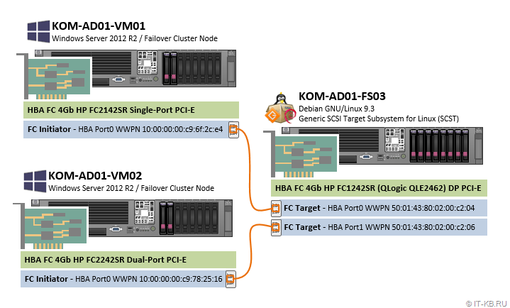
В данной заметке мы не будем уделять внимания процедуре построения кластера Hyper-V, как таковой, а сделаем упор на описании процесса настройки FC Target на базе SCST и продемонстрируем дальнейшую возможность использования созданного нами дискового массива в качестве общего тома в кластере Windows Failover Cluster.
Подготовка сервера под роль СХД
Конфигурация выделенного сервера под роль СХД подразумевает ряд действий, которые нам нужно будет последовательно выполнить в дальнейшем. Готовя старый сервер под любую новую задачу, всегда стоит начать с базовой проверки состояния оборудования и обновления всех доступных на данный момент времени прошивок firmware, например, как это было описано ранее в начале заметки Установка CentOS Linux 7.2 на сервер HP ProLiant DL360 G5 с поддержкой драйвера контроллера HP Smart Array P400i.
Если говорить о базовой установке современной версии ОС Debian Linux на аппаратную платформу HP ProLiant DL380 Gen5, то ранее уже было опубликован ряд соответствующих заметок:
- Особенность установки Debian Linux Stretch с подключением firmware из non-free репозиториев (на примере bnx2)
- Установка HPE System Management Tools на сервер с ОС Debian Linux Stretch, а также HP Array Configuration Utility (ACU) для управления устаревшими контроллерами HP Smart Array
Таким образом мы предполагаем, что на сервер KOM-AD01-FS03 уже установлена ОС Debian GNU/Linux 9.3 и утилиты управления HP.
Получаем Firmware для FC HBA QLogic
По умолчанию в Debian нет поддержки firmware QLogic, так как этот тип ПО относится к категории non-free, поэтому установленный в сервер оптический адаптер FC HBA QLogic, который требуется нам для дальнейшей организации FC Target, просто так не заработает. В процессе загрузки системы драйвер, обеспечивающий работу HBA QLogic (модуль ядра qla2xxx), выдаст нам сообщение о невозможности загрузки микрокода HBA «Direct firmware load for ql2400_fw.bin failed with error -2«:
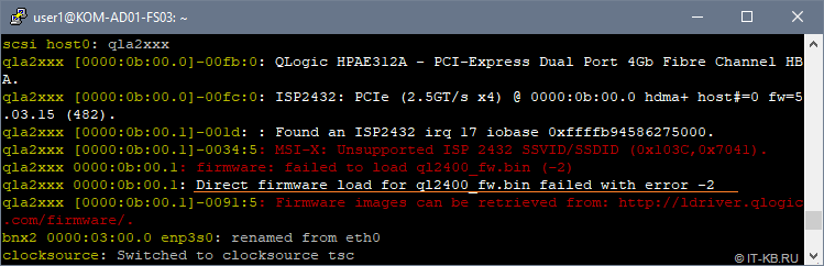
В целом картина по обнаружению и загрузке устройств qla2xxx в нашем случае выглядит так:
# dmesg -t | grep -i qla

qla2xxx ... QLogic Fibre Channel HBA Driver: 8.07.00.38-k.
qla2xxx ... Found an ISP2432 irq 16 iobase 0xffffb94586265000.
qla2xxx ... MSI-X: Unsupported ISP 2432 SSVID/SSDID (0x103C,0x7041).
qla2xxx ... firmware: failed to load ql2400_fw.bin (-2)
qla2xxx ... Firmware images can be retrieved from: http://ldriver.qlogic.com/firmware/.
scsi host0: qla2xxx
qla2xxx ... QLogic HPAE312A - PCI-Express Dual Port 4Gb Fibre Channel HBA.
qla2xxx ... ISP2432: PCIe (2.5GT/s x4) @ 0000:0b:00.0 hdma+ host#=0 fw=5.03.15 (482).
qla2xxx ... Found an ISP2432 irq 17 iobase 0xffffb94586275000.
qla2xxx ... MSI-X: Unsupported ISP 2432 SSVID/SSDID (0x103C,0x7041).
qla2xxx ... firmware: failed to load ql2400_fw.bin (-2)
qla2xxx ... Direct firmware load for ql2400_fw.bin failed with error -2
qla2xxx ... Firmware images can be retrieved from: http://ldriver.qlogic.com/firmware/.
scsi host5: qla2xxx
qla2xxx ... QLogic HPAE312A - PCI-Express Dual Port 4Gb Fibre Channel HBA.
qla2xxx ... ISP2432: PCIe (2.5GT/s x4) @ 0000:0b:00.1 hdma+ host#=5 fw=5.03.15 (482).
qla2xxx ... Cable is unplugged...
qla2xxx ... Cable is unplugged...
Для работы с контроллером HBA QLogic встроенный в Linux драйвер qla2xxx будет пытаться использовать микрокод из каталога /lib/firmware. Поэтому нам нужно обеспечить наличие в этом каталоге совместимой с драйвером версии firmware.
Получить микрокод firmware можно из двух разных мест:
- c сайта QLogic http://ldriver.qlogic.com/firmware/, скачав соответствующие bin-файлы (в нашем случае, как минимум, требуется файл ql2400_fw.bin) и разместив эти файлы в каталоге /lib/firmware/
- из репозиториев Debian, подключив репозитории non-free и установив пакет qlogic-firmware.
Можно обнаружить то, что микрокод ql2400_fw.bin, доступный на сайте QLogic, судя по описанию CURRENT_VERSIONS имеет версию 7.03.00, в то время, как версия в репозиториях Debian Stretch, судя по описанию к пакету firmware-qlogic, — 8.03.00. Тут может возникнуть соблазн использовать более новую версию прошивки из репозиториев Debian. Однако, нужно учитывать то, что между используемым нами микрокодом HBA и драйвером должна быть обеспечена полная совместимость.
Здесь стоит отдельно остановится на том, почему мы будем использовать описанную далее конфигурацию, в которой вместо поставляемого в составе Debian драйвера qla2xxx будет использоваться предлагаемый разработчиками SCST драйвер qla2x00t. Ведь, казалось бы, использование микрокода, устанавливаемого из пакетов и драйвер, поставляемый в составе Linux, несколько упрощают процедура настройки. Однако, здесь есть несколько «НО».
Во первых такая конфигурация не будет считаться правильной с точки зрения разработчиков SCST, так как свое ПО они разрабатывают именно под свою версию драйвера qla2x00t. Драйвер qla2x00t, который, как я понял, является «форкнутым» несколько лет назад и отлаженным разработчиками SCST драйвером qla2xxx. В ходе изучения этого вопроса, где-то в мейл-листе SCST мне даже попадалась на глаза дискуссия на эту тему, но к сожалению не сохранил ссылку.
Во вторых, использование драйвера qla2x00t, предполагает использование совместимой с ним версии микрокода QLogic. Мои эксперименты показали то, что текущая версия драйвера qla2x00t не приводит к адекватной работе FC Target при условии использования микрокода, поставляемого в пакете firmware-qlogic из репозиториев Debian. Именно поэтому нужно использовать тот микрокод, который доступен на сайте QLogic.
Таким образом, в нашей конфигурации для обеспечения работы FC HBA QLogic под задачу FC Target будет использоваться микрокод с сайта QLogic и драйвер от SCST (qla2x00t).
Скачаем микрокод в каталог /lib/firmware и вызовем процедуру переcборки загружаемого образа initial ramdisk (initrd):
# cd /lib/firmware
# wget http://ldriver.qlogic.com/firmware/ql2500_fw.bin
# wget http://ldriver.qlogic.com/firmware/ql2400_fw.bin
# wget http://ldriver.qlogic.com/firmware/ql2322_fw.bin
# wget http://ldriver.qlogic.com/firmware/ql2300_fw.bin
# wget http://ldriver.qlogic.com/firmware/ql2200_fw.bin
# wget http://ldriver.qlogic.com/firmware/ql2100_fw.bin
# update-initramfs -u
# reboot
После этого выполним перезагрузку сервера и после загрузки системы снова посмотрим в лог загрузки через утилиту dmesg и убедимся в том, что микрокод HBA успешно загружен в процессе запуска системы
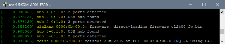
Далее перейдём к отключению встроенного в Linux драйвера qla2xxx.
Отключаем стандартный драйвер qla2xxx
Отключаем стандартный модуль ядра Linux с драйвером qla2xxx, исключаем этот модуль из загрузочного образа initrd и отправляем сервер в перезагрузку:
# rmmod qla2xxx
# echo blacklist qla2xxx >/etc/modprobe.d/blacklist-qla2xxx.conf
# update-initramfs -u
# reboot
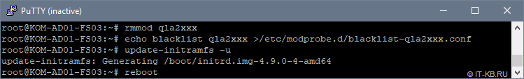
После перезагрузки убеждаемся в том, что отключенный ранее модуль действительно не загружен и его сообщений не было в процессе загрузки системы
# lsmod | grep qla
# dmesg | grep qla
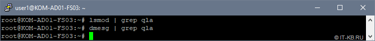
Как видим, вывод отсутствует, то есть стандартный драйвер qla2xxx успешно отключен и больше не используется.
Получаем исходные коды ядра Linux и SCST
Устанавливаем пакеты, необходимые для сборки и исходные коды используемой у нас версии ядра Linux:
# apt-get install -y linux-headers-$(uname -r) fakeroot kernel-wedge build-essential makedumpfile libncurses5 libncurses5-dev lsscsi patch subversion bc devscripts
Выходим в непривилегированное окружение стандартного пользователя Linux, где будем заниматься правкой и сборкой исходных кодов. Создаём в домашнем каталоге текущего пользователя подкаталог, в котором будем работать с исходниками, например ~/Build, переходим в него и выполняем загрузку исходного кода используемого у нас ядра Linux:
$ mkdir ~/Build
$ cd ~/Build
$ apt-get source linux-source-4.9
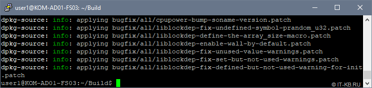
Сюда же, в каталог ~/Build выполняем загрузку исходных кодов актуальной версии SCST:
$ cd ~/Build
$ svn co https://svn.code.sf.net/p/scst/svn/trunk scst
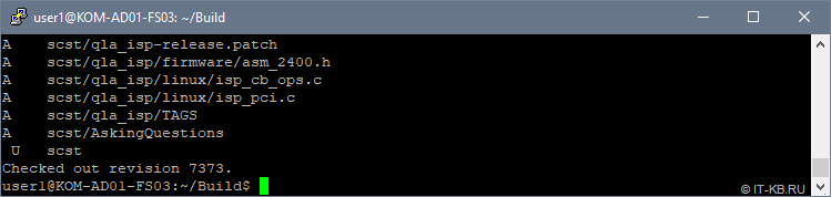
Кстати, в моём случае svn не захотел использовать переменные окружения текущего пользователя, описывающие параметры прокси в файле ~/.profile, поэтому на время пришлось открыть машине прямой доступ в интернет.
Посмотрим, что в конечном итоге получилось в нашем сборочном каталоге:
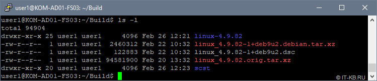
Накладываем патчи SCST на исходные коды ядра Linux
Давайте заглянем в исходные коды SCST и посмотрим то, какие патчи там имеются для ядра Linux используемой у нас 4-ой версии:
$ find ~/Build/scst -name *4.*.patch
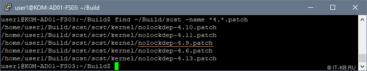
Как видим, для нашей версии ядра Linux 4.9 имеется патч nolockdep-4.9.patch, который мы и будем накладывать на исходные коды ядра Linux.
Переходим в каталог с файлами исходных кодов ядра Linux и накладываем патч:
$ cd ~/Build/linux-4.9.82/
$ patch -p1 < ~/Build/scst/scst/kernel/nolockdep-4.9.patch
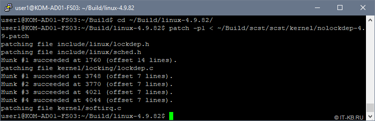
Меняем в исходных кодах ядра драйвер qla2xxx на драйвер от SCST — qla2x00t
Заменяем драйвер в исходниках ядра Linux на тот, что в предлагается в исходниках SCST. Для этого сначала переименуем каталог с оригинальными исходниками драйвера, поставляемыми вместе с исходниками ядра Linux. Затем слинкуем каталог с исходниками драйвера из поставки SCST на имя каталога, которое ранее использовалось исходниками оригинального драйвера
$ mv ~/Build/linux-4.9.82/drivers/scsi/qla2xxx ~/Build/linux-4.9.82/drivers/scsi/qla2xxx_orig
$ ln -s ~/Build/scst/qla2x00t ~/Build/linux-4.9.82/drivers/scsi/qla2xxx
Проверим, что получилось:
$ ls -la ~/Build/linux-4.9.82/drivers/scsi/ | grep qla2xxx
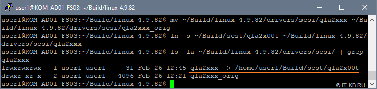
Выполняем конфигурацию ядра Linux
Если по какой-то причине Вы собираете 32-битное ядро, то обратите внимание на рекомендации, данные в пункте 11 статьи How to Configure the FC QLogic Target Driver for 22xx/23xx/24xx/25xx/26xx Adapters.
В каталоге с пропатченными исходными кодами ядра запускаем режим конфигурирования параметров ядра
$ cd ~/Build/linux-4.9.82/
$ make menuconfig
Конфигурация пары описанных далее параметров подсмотрена в статье Linux Fibre Channel SCSI Target using SCST. На самом деле она не является обязательной, но предлагается в качестве дополнительного тюнинга для предположительного улучшения показателей производительности работы Linux с блочными устройствами.
В открывшемся интерактивном режиме настройки параметров ядра перейдём в пункт «Enable the block layer«
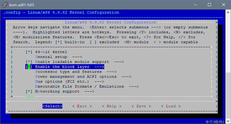
В списке опций выберем «IO Schedulers» и удостоверимся в том, что в качестве планировщика по умолчанию «Default I/O Scheduler» выбран вариант «CFQ«:
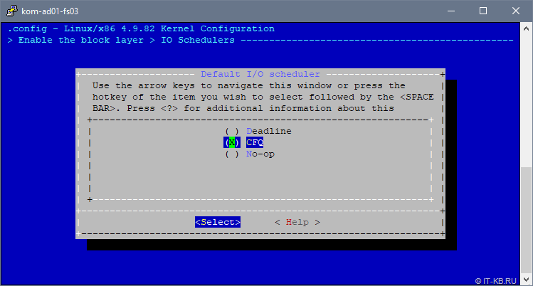
Подробнее про разные типы планировщиков, в том числе и про CFQ, на русском языке можно прочитать, например здесь. А в заметке Linux I/O Scheduler. Выбираем оптимальный можно найти нехитрый скрипт, для проведения экспериментов по самостоятельному выявлению оптимального планировщика.
Далее переходим в пункт «Processor type and features» и выбираем опцию «Preemption Model«. Переключаем опцию в значение «No Forced Preemption (Server)»:
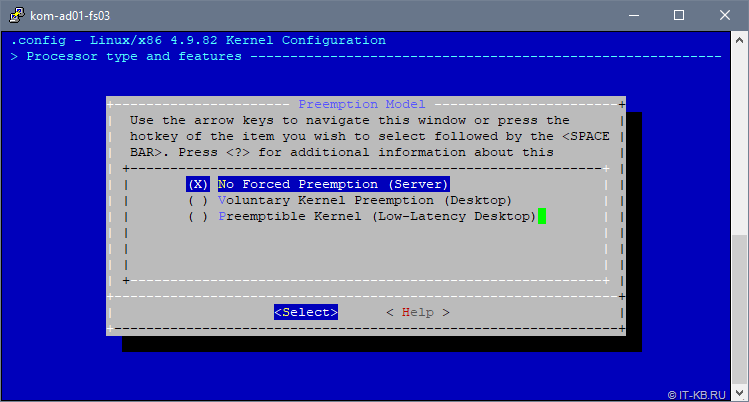
Для понимания сути этой опции приведу цитату:
No Forced Preemption (Server) - Это традиционная для Linux модель с приоритетным прерыванием обслуживания (preemption model), она обеспечивает хорошее время отклика (latency), но не дает никаких гарантий, и при её применении возможны случайные длительные задержки. Выбирайте эту опцию, если Вы собираете ядро для сервера или для научных/вычислительных систем, или если Вы хотите увеличить «сырую» вычислительную мощность ядра.
Далее с верхнего уровня переходим последовательно в пункты «Device Drivers» > «SCSI device support» > «SCSI low level drivers» и убеждаемся в том, что для драйвера QLA2XXX присутствует и включена built-in опция «QLogic 2xxx target mode support«
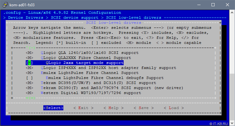
Затем переходим в раздел настроек «General setup» и выбираем пункт «Local version – append to kernel release«, чтобы добавить в имя ядра строку, идентифицирующую наше кастомизированное ядро:
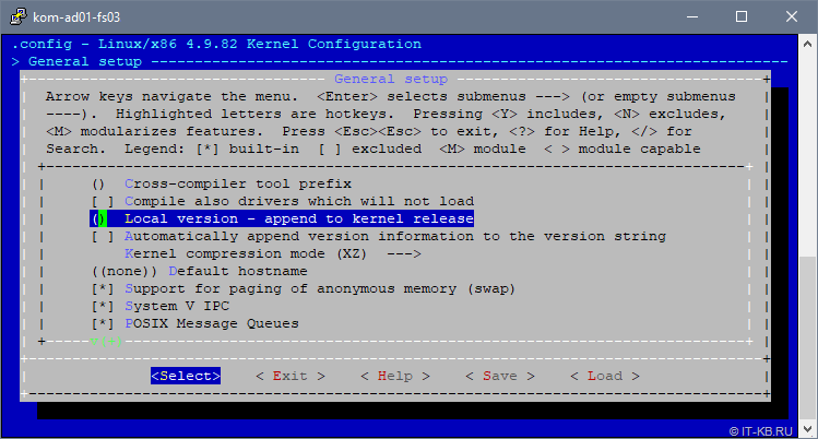
Введём понятный нам постфикс, который будет добавлен к имени ядра при сборке, например «-scst-enabled«
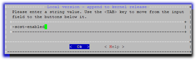
При выходе из интерактивного режима конфигурирования ядра ответим утвердительно на вопрос о сохранении:
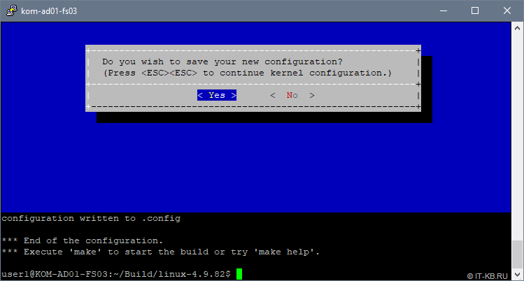
Собираем и устанавливаем ядро Linux
Находясь в текущем каталоге (напоминаю, что мы работаем в каталоге с пропатченными исходными кодами ядра, параметры которого только что были настроены) запускаем процесс компиляции ядра и сборки deb-пакетов:
$ cd ~/Build/linux-4.9.82/
$ make deb-pkg clean
Процесс может занять длительное время, в зависимости от проворности процессора. По окончании процесса мы получим несколько deb-пакетов в каталоге верхнего уровня, относительно каталога компиляции:
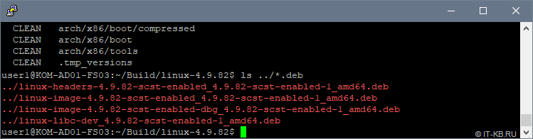
Устанавливаем пакеты нашего кастомизированного ядра Linux:
$ cd ~/Build
$ sudo dpkg -i linux-image-4.9.82-scst-enabled_4.9.82-scst-enabled-1_amd64.deb
$ sudo dpkg -i linux-headers-4.9.82-scst-enabled_4.9.82-scst-enabled-1_amd64.deb
В ходе установки автоматически будет обновлён загрузочный образ initrd
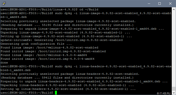
После этого выполняем перезагрузку сервера. В процессе загрузки системы, если заглянем в текущий список ядер в загрузчике GRUB, то увидим, что по умолчанию для загрузки системы используется наше кастомизированное ядро
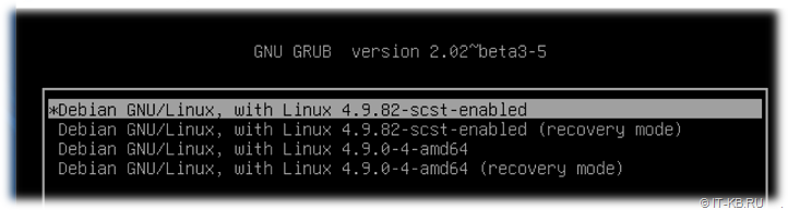
Для того, чтобы собранное нами кастомизированное ядро Linux не обновилось в дальнейшем в процессе обновления всех пакетов системы (не было заменено в загрузчике новой версией ядра из пакета linux-image-amd64), настроим исключение для менеджера пакетов apt.
# dpkg --get-selections | grep -E "linux-(image|headers)"
# apt-mark hold linux-image-amd64
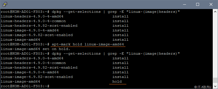
Теперь давайте попробуем выполнить обновление кеша менеджера пакетов и убедимся в том, что не смотря на то, что новая версия пакета linux-image-amd64 в репозиториях присутствует, при установке обновлений данный пакет не устанавливается, так как ранее мы его пометили в hold:
# apt-get update
# apt list --upgradable
# apt-get upgrade
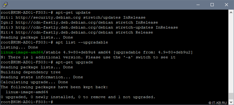
С ядром закончили, переходим к сборке SCST.
Компилируем и устанавливаем SCST
Переходим в каталог с исходными кодами SCST, компилируем и устанавливаем SCST:
$ cd ~/Build/scst/
$ make 2release
$ sudo BUILD_2X_MODULE=y CONFIG_SCSI_QLA_FC=y CONFIG_SCSI_QLA2XXX_TARGET=y make all install
После окончания компиляции и установки убедимся в том, что нужные нам для работы модули ядра присутствуют в системе:
$ ls -l /lib/modules/`uname -r`/extra/
$ ls -l /lib/modules/`uname -r`/extra/dev_handlers
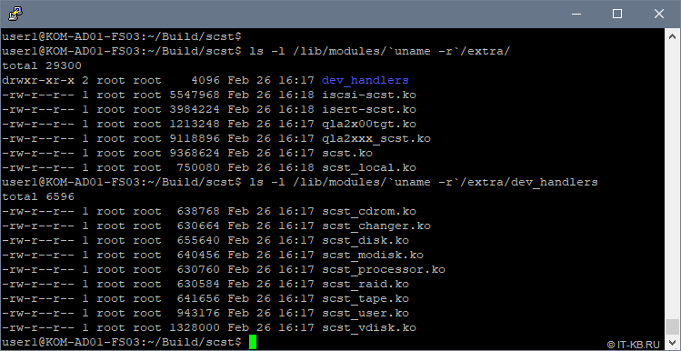
Убедимся в том, что для нужных нам модулей ядра, при попытке их загрузки не возникает никаких ошибок:
$ sudo modprobe scst
$ sudo modprobe qla2x00tgt
$ sudo modprobe qla2xxx_scst
$ sudo modprobe scst_vdisk
$ sudo modprobe scst_user
$ sudo modprobe scst_disk
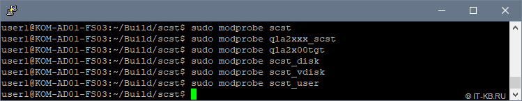
Если при попытке загрузки модулей возникает ошибка типа «modprobe: FATAL: Module qla2x00tgt not found in directory /lib/modules/4.9.82-scst-enabled«, но соответствующий ko-файл при этом в каталоге присутствует, попробуйте выполнить обновление зависимостей модулей командой:
$ sudo depmod --all
Убедившись в том, что все нужные нам модули загружаются без ошибок, настраиваем их автоматическую загрузку при старте системы, дописав названия модулей в конец конфигурационного файла /etc/modules
$ cat /etc/modules

# /etc/modules: kernel modules to load at boot time.
#
# This file contains the names of kernel modules that should be loaded
# at boot time, one per line. Lines beginning with "#" are ignored.
#
scst
qla2xxx_scst
qla2x00tgt
scst_vdisk
scst_user
scst_disk
Перезагрузим систему, чтобы убедиться в том, что в процессе загрузки модули SCST загружаются успешно. Проверим это в выводе команды dmesg
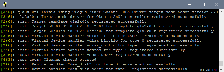
Далее мы рассмотрим пример настройки и загрузки рабочей конфигурации SCST, но прежде нам потребуется собрать и установить утилиту управления scstadmin.
Компилируем и устанавливаем SCSTAdmin
Снова входим в режим непривелегированного пользователя, переходим в наш каталог с исходными файлами scst в подкаталог ../scstadmin и даём последовательно команды компиляции и установки:
$ cd ~/Build/scst/scstadmin/
$ make
$ sudo make install
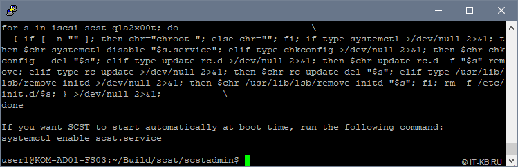
Последуем совету, который будет выдан нам в процессе установки, и включим автоматическую загрузку службы scst.service при старте системы:
$ sudo systemctl enable scst.service
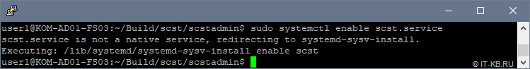
Теперь давайте спросим у scstadmin, какие типы HANDLER и TARGET_DRIVER нам доступны для настройки нашей конфигурации:
# scstadmin -list_handler
# scstadmin -list_driver
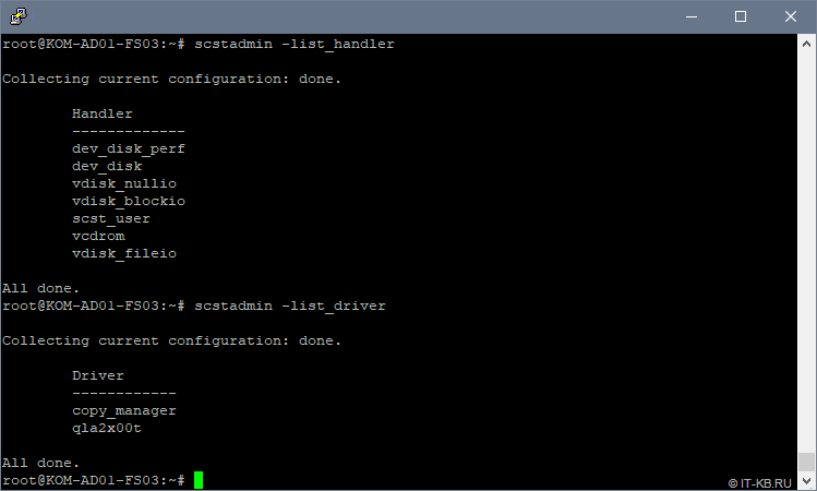
Как видим, в списке поддерживаемых scstadmin драйверов есть интересующий нас драйвер qla2x00t.
Посмотрим информацию о доступных TARGET, которыми мы можем оперировать в конфигурации:
# scstadmin -list_target
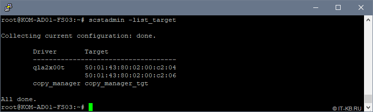
Теперь можно переходить к настройке конфигурации SCST, но перед этим нужно определиться с дисковыми ресурсами, которые мы будем транслировать с нашего Linux-сервера на хосты виртуализации через FC Target.
Настраиваем дисковые ресурсы Linux-сервера
Для построения кластера высоко-доступных виртуальных машин Hyper-V нам, как минимум, потребуется один выделенный диск под том CSV, на котором будут размещаться виртуальные машины. Дополнительно нам не помешает иметь ещё один кластерный диск для роли диска-свидетеля, который нужен для организации кластерного кворума Windows Failover Cluster.
На имеющейся в нашем распоряжении конфигурации из 6 дисков в утилите управления HPE SSA, об установке которой мы говорили ранее, создан массив Smart Array (Array B). В этом массиве созданы 2 логических диска:
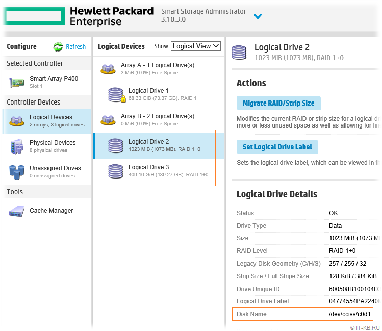
Логический диск «Logical Drive 2» размером в 1GB определён в нашей Linux-системе, как блочное устройство /dev/cciss/c0d1. Этот диск будет использоваться в качестве диска-свидетеля. Есть мнение, что при построении кластеров Windows Failover Cluster в качестве диска-свидетеля правильней выбирать диск не связанный напрямую с диском, который будет использоваться под кластеризуемые сервисы, как например, в нашем случае — под размещение ВМ. Ну или по крайней мере эти диски лучше иметь из разных RAID массивов. Но в моём случае конфигурация весьма ограниченная, поэтому используется такая вот упрощённая схема.
Логический диск «Logical Drive 3«, которому выдана вся оставшаяся ёмкость дискового массива, определён в Linux, как блочное устройство /dev/cciss/c0d2. Этот диск будет использоваться в качестве диска для хранения ВМ. В последствии данный диск будет преобразован в CSV
Настраиваем конфигурацию SCST
По умолчанию основная служба scst.service будет загружаться без использования какой-либо конфигурации. Поэтому нам потребуется создать основной конфигурационный файл scst.conf, описать в нём нужную нам конфигурацию FC Target и обеспечить его автоматическую загрузку при старте системы.
Создадим отсутствующий по умолчанию файл scst.conf:
# nano /etc/scst.conf
Наполним его содержимым примерно следующего характера (основную информацию относительно написания конфигурационного файла можно посмотреть в man scst.conf):
HANDLER vdisk_fileio {
        #
        # HP Smart-Array P400 Controller -  Array B - Logical Drive 2
        #
        DEVICE FS03-P400-B-LD2 {
            filename /dev/cciss/c0d1
        }
        #
        # HP Smart-Array P400 Controller -  Array B - Logical Drive 3
        #
        DEVICE FS03-P400-B-LD3 {
            filename /dev/cciss/c0d2
        }
}

TARGET_DRIVER qla2x00t {
        #
        # HBA HP QLogic QLE2462 - Port 0
        #
       TARGET 50:01:43:80:02:00:c2:04 {
                enabled 1
                #
                # Access for host KOM-AD01-VM02
                #
                GROUP Host-VM02 {
                        LUN 0 FS03-P400-B-LD2
                        LUN 1 FS03-P400-B-LD3
                        INITIATOR 10:00:00:00:c9:78:25:16
                }
        }
        #
        # HBA HP QLogic QLE2462 - Port 1
        #
       TARGET 50:01:43:80:02:00:c2:06 {
                enabled 1
                #
                # Access for host KOM-AD01-VM01
                #
                GROUP Host-VM01 {
                        LUN 0 FS03-P400-B-LD2
                        LUN 1 FS03-P400-B-LD3
                        INITIATOR 10:00:00:00:c9:6f:2c:e4
                }
        }
}
В целом структура конфигурационного файла SCST очень наглядна и логична.
В нашем примере в разделе HANDLER описаны имеющиеся в нашем распоряжении блочные устройства, которые нужно транслировать на FC Target. Типы поддерживаемых устройств мы проверяли ранее командой scstadmin -list_handler. Каждое блочное устройство описывается в отдельной секции DEVICE. Имена дисковым устройствам SCST в нашем примере назначены таким образом, чтобы сразу было очевидно физическое месторасположение этих устройств.
В разделе TARGET_DRIVER описаны так называемые цели – Target. Типы поддерживаемых драйверов мы проверяли ранее командой scstadmin -list_driver. Каждый порт оптического контроллера, который мы хотим превратить в FC Target имеет отдельную секцию TARGET.
В свою очередь для каждой отдельной цели (TARGET) мы описываем группу GROUP, в которой определяем перечень устройств (из HANDLERDEVICE) с номерами LUN и WWPN портов оптических адаптеров хостов, которым нужно предоставить доступ к данным LUN-ам через данный TARGET (WWPN портов со стороны FC Initiator).
Подготовив конфигурационный файл, заставим SCST перечитать конфигурацию:
# scstadmin -conf /etc/scst.conf

Если scstadmin отказывается загружать созданный нами вручную конфигурационный файл scst.conf, то вполне возможно, что где-то допущена синтаксическая ошибка. В таком случае правку конфигурации можно выполнять через набор встроенных команд в утилиту scstadmin (смотреть встроенную справку scstadmin --help)
В любом случае при попытке загрузки созданной нами конфигурации никаких ошибок быть не должно и соответствующие LUN-ы должны в этот момент стать доступны на стороне хостов виртуализации. Однако, прежде чем, переходить к использованию LUN-ов на стороне хостов Hyper-V нам нужно решить ещё одну задачу – обеспечить автоматическую загрузку созданной нами конфигурации в процессе загрузки Linux.
Настраиваем автоматическую загрузку конфигурации SCST
Создадим новую службу (systemd unit), например с именем scst-config.service, описав её конфигурацию в каталоге /etc/systemd/system:
# nano /etc/systemd/system/scst-config.service
Наполним файл содержимым:
[Unit]
Description=SCST Configuration Service
After=scst.service

[Service]
Type=oneshot
RemainAfterExit=yes
ExecStart=/usr/local/sbin/scstadmin -config /etc/scst.conf
StandardOutput=journal

[Install]
WantedBy=multi-user.target
Включим автозагрузку службы при старте системы:
# systemctl enable scst-config.service
Перезагрузим сервер и убедимся в том, что наша служба успешно стартовала после загрузки ОС:
# systemctl status scst-config.service
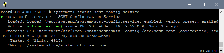
Проверим лог, созданной нами службы scst-config.service, чтобы увидеть вывод утилиты scstadmin в процессе загрузки конфигурации из файла /etc/scst.conf:
# journalctl --unit scst-config.service --output cat
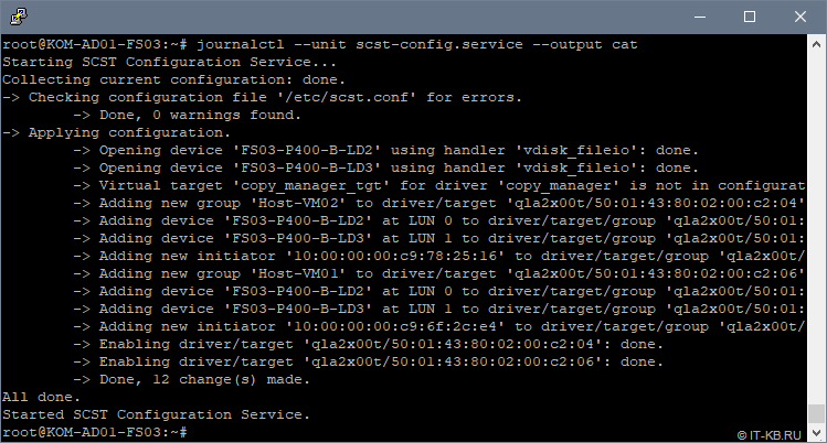
Как видим, конфигурация SCST загружена успешно и никаких ошибок и предупреждений в процессе загрузки нет.
Настроенная нами служба scst-config.service устроена таким образом, что её перезапуск равнозначен команде scstadmin -config /etc/scst.conf, то есть если нужно заставить SCST перечитать конфигурацию scst.conf, то для этого достаточно перезапустить службу:
# systemctl status scst-config.service
При этом остановка службы никак не повлияет на работу SCST.
Теперь можем переходить к инициализации транслируемых через FC Target дисковых устройств на хостах виртуализации.
Проверяем доступность LUN-ов на хостах виртуализации
На любом из хостов виртуализации откроем консоль Device Manager и удостоверимся в том, что в разделе Disk drives присутствуют созданные нами ранее в конфигурации SCST дисковые устройства. Затем перейдём в консоль управления дисками Disk Management и переведём соответствующие дисковые устройства в состояние Online:
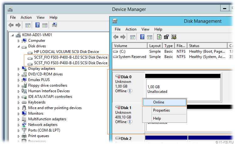
После того, как диски переведены в Online, выполняем инициализацию этих дисков (Initialize Disk), затем создаём на диске простой том NTFS (New Simple Volume…)
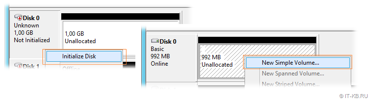
При форматировании первого диска, который будет использоваться в будущем кластере в качестве диска свидетеля, присвоим букву диска, например Q. Второму диску, который будет использоваться в кластере в качестве CSV для размещения виртуальных машин, при форматировании букву диска не присваиваем, так как в дальнейшем этот диск будет смонтирован в каталог C:ClusterStorage на обоих узлах кластера.
В результате на первом хосте мы получим примерно следующую картину
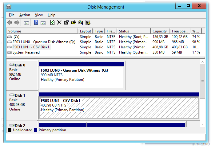
Теперь подключимся ко второму хосту и убедимся в том, что там оба диска также доступны, но они при этом будут находится в состоянии Offline.
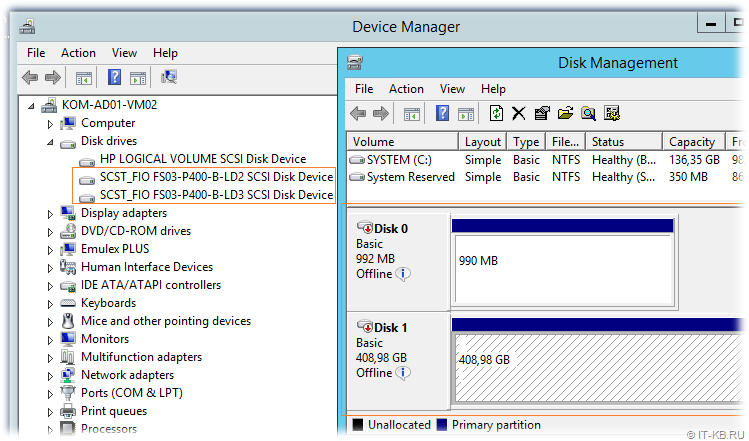
Как видим, диски доступны на обоих хостах виртуализации и подготовлены для того, чтобы использовать их для построения кластера Windows Failover Cluster.
Выполняем валидацию LUN-ов и создаём кластер Windows Failover Cluster
Сразу скажу, что мы не будем рассматривать все подготовительные процедуры, необходимые для создания кластера Windows Failover Cluster, а заострим внимание лишь на тех моментах, которые имеют непосредственное отношение к работе с дисковыми ресурсами, подключенными к хостам виртуализации с Linux-сервера c SCST.
Предполагаем, что на обоих хостах виртуализации у нас уже установлены компоненты Windows Failover Cluster и настроены выделенные сетевые адаптеры для меж-узлового обмена. Открываем на любом из хостов оснастку Failover Cluster Manager (Cluadmin.msc) и вызываем мастер проверки конфигурации кластера Validate a Configuration Wizard. Добавив в мастер оба наших хоста виртуализации, запускаем процедуру проверки конфигурации хостов на предмет возможности включения этих хостов в кластер.
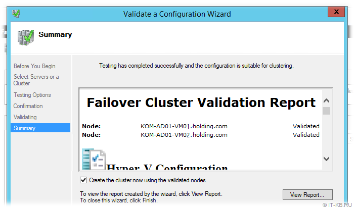
В результате мы должны удостовериться в том, что презентованные с Linux-хоста с SCST дисковые устройства успешно проходят все проверки. Детальную информацию о выполненных проверках можно посмотреть, пройдя по гиперссылкам в отчёте в разделе Storage
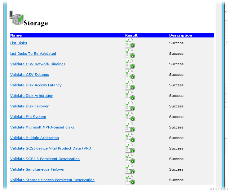
В общем-то уже на данном этапе мы видим, что поставленная цель превращения обычного сервера в СХД нами достигнута. Далее на базе проверенной конфигурации хостов создаём опорный кластер Windows Failover Cluster, преобразуем диск в CSV, а затем создаём в кластере высоко-доступную ВМ Hyper-V. После проверяем штатное перемещение ВМ между узлами кластера, а также проверяем обработку отказа узла в кластере.
Выводы
Итак, базовая кластерная конфигурация Hyper-V с подключённой по оптике дисковой ёмкостью собрана нами в простом бюджетном варианте с использованием свободно-распространяемого ПО SCST на базе современной версии Debian Linux на старом серверном оборудовании. Отдельно приобретаемые под эту задачу адаптеры HBA старых поколений FC 4G сейчас стоят довольно скромных денег. Хотите скоростей, пожалуйста, используйте на стороне сервера SCST и подключаемых к нему хостов более современные адаптеры HBA FC 8G или даже 16G
Если Linux-сервер c SCST подключать не напрямую к хостам, а к фабрикам FC SAN, то можно отдавать дисковую ёмкость бОльшему количеству хостов виртуализации, используя более широкие кластерные конфигурации Windows Failover Cluster.
Разумеется описанное решение имеет свои «узкие места».
Если сервер SCST собран без учёта избыточности аппаратных компонент, как, например, в нашем случае используется только один контроллер FC HBA QLogic, то выход из строя таких компонент может привести к недоступности всех виртуальных машин (дисковая ёмкость станет недоступна сразу всем хостам кластера). В качестве решения можно расширить конфигурацию на сервере SCST вторым контроллером, а на узлах использовать, двух-портовые HBA или пару одно-портовых HBA, чтобы можно было использовать multipath-подключение к дисковым ресурсам SCST, которое обработку отказа путей подключения.
Дополнительные источники информации:
- SCST Howto — How to Configure the FC QLogic Target Driver for 22xx/23xx/24xx/25xx/26xx Adapters
- thejimmahknows.com — Linux Fibre Channel SCSI Target using SCST
- debianforum.de — FC Target (SAN) unter Debian 8 / Jessie
- nandydandyoracle — SCST Debian Package Build from Source (Ubuntu 17.04)
- Хабрахабр — Бюджетное SAN-хранилище на LSI Syncro
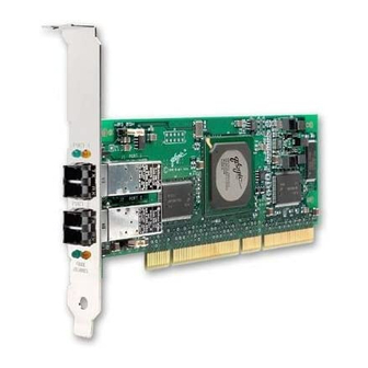
-
Contents
-
Table of Contents
-
Troubleshooting
-
Bookmarks
Quick Links
Fibre Channel Adapter for VMware ESX
User’s Guide
FC0054606-00 A
Related Manuals for Qlogic Fibre Channel Adapter
Summary of Contents for Qlogic Fibre Channel Adapter
-
Page 1
Fibre Channel Adapter for VMware ESX User’s Guide FC0054606-00 A… -
Page 2: Document Revision History
QLogic Corporation reserves the right to change product specifications at any time without notice. Applications described in this document for any of these products are for illustrative purposes only. QLogic Corporation makes no representation nor warranty that such applications are suitable for the specified use without further testing or modification.
-
Page 3: Table Of Contents
Configuration Identifying QLogic FC Adapters on VMware ESX ….Using VI Client……… . .
-
Page 4
Fibre Channel Adapter for VMware ESX User’s Guide Configuring the Driver Parameters……. . Deploying NPIV for VMware ESX/ESXi . -
Page 5: Preface
This guide provides detailed instructions on the installation, configuration, and troubleshooting of QLogic FC adapters on VMware ESX/ESXi. It also provides details on the use of QLogic FC adapter features to enhance the value of server virtualization using VMware ESX/ESXi. Such features include virtual adapter configuration using N_Port ID Virtualization (NPIV) and “boot from SAN”…
-
Page 6: What’s In This Guide
This user’s guide provides a brief introduction to the FC adapter offerings from QLogic at a broad level. The main focus of this guide is to explain the FC adapter software driver features, management tools available on VMware ESX/ESXi, and the supported features.
-
Page 7
Text in ALL CAPITALS indicates the name of a key that you press on the keyboard. For example: On the QLogic BIOS banner screen, press CTRL+Q. Text in italics indicates emphasis, terms, or document titles. For example: Refer to the VMware IO Compatibility Guide. -
Page 8: License Agreements
License Agreements Refer to the QLogic Software End User License Agreement for a complete listing of all license agreements affecting this product. Technical Support Customers should contact their authorized maintenance provider for technical support of their QLogic switch products. QLogic-direct customers may contact QLogic Technical Support;…
-
Page 9: Hardware And Software Components
Hardware and Software Components This chapter provides details about QLogic FC adapters for VMware, including: “Hardware Components” on page 1-1 “Software Components” on page 1-3 “QLogic FC Adapters Supported on VMware ESX/ESXi” on page 1-4 Hardware Components A typical QLogic FC adapter includes the following major components:…
-
Page 10: Fc Adapter Components
The non-volatile memory, also referred to as Flash memory, contains the boot code run by the RISC processor (see 1) when the adapter is powered up. On QLogic FC adapter 2400 series and later, the Flash memory contains multiple boot images—the FCode, x86 BIOS, and EFI—to support multi-boot capability on different platforms.
-
Page 11: Software Components
QLogic adapter. This type of configuration is referred to as boot from SAN. OS Driver For all QLogic FC adapters currently supported on VMware ESX/ESXi, the driver is supported natively with ESX;…
-
Page 12: Management Tools And Utilities
FC adapter management by means of scripting and interactive mode. QLogic FC Adapters Supported on VMware ESX/ESXi For a complete list of QLogic FC adapters supported on VMware ESX/ESXi, refer to the VMware IO Compatibility Guides located as follows: VMware ESX 3.5: http://www.vmware.com/pdf/vi35_io_guide.pdf…
-
Page 13: Installation
“Installing the Hardware” on page 2-2 “Installing the Driver” on page 2-3 “Installing SANsurfer Management Tools” on page 2-3 Supported Features When properly installed, QLogic FC adapters for VMware ESX support the following features: Topologies—FC-AL, FC-AL2, point-to-point, and switched fabric. Protocols—FCP-3-SCSI, FC-tape (FCP-2).
-
Page 14: Installing The Hardware
Installation Installing the Hardware Installing the Hardware Adapter hardware installation requires that you open the computer and locate the appropriate bus slot for housing the adapter, as detailed in the following steps. Figure 2-1 shows the hardware placement. ADAPTER LEVER SCREW 64-BIT PCI-X SLOT ADAPTER…
-
Page 15: Installing The Driver
IP address or host name of the ESX host on which the qlremote agent is installed. When SANsurfer FC HBA Manager is connected to the qlremote agent, you can use it to view and manage the QLogic adapters. FC0054606-00 A…
-
Page 16: Downloading Sansurfer Fc Hba Manager-Vmware
# service portmap restart SANsurfer FC HBA Manager requires that you select the download link to the package for your operating system, either from an installation CD or the QLogic Web site. To install SANsurfer FC HBA Manager on VMware:…
-
Page 17: Downloading Sansurfer Fc Hba Manager-Linux
Install the qlremote agent on your ESX host using silent mode as follows: # ./standalone_sansurfer5.0.1b33_linux_install.bin -i silent To install SANsurfer FC HBA Manager on Linux or Windows: Go to the QLogic Driver Downloads / Documentation page at the following URL: http://driverdownloads.qlogic.com/QLogicDriverDownloads_UI/default.aspx Click the by Operating System button, and then select Fibre Channel HBAs, Linux (or Windows) OS, and the specific OS version.
-
Page 18: Installing Sansurfer Fc Hba Cli
Follow these steps to download and install the SANsurfer FC HBA CLI utility. To install SANsurfer FC HBA CLI: From the QLogic Web site or the SANsurfer Management Suite CD-ROM, download the scli-x.xx.xx-xx.i386.rpm.gz file to your local machine. (In the file name, x.xx.xx indicates the current version of SANsurfer FC HBA CLI.
-
Page 19: Configuration
Using VI Client Using Console OS Using VI Client You can use the VM Infrastructure Client (VI Client) to identify QLogic FC adapters on a VMware ESX system. To identify QLogic FC adapters using VI Client: Start VM Infrastructure Client and select the host you want.
-
Page 20: Using Console Os
Identifying QLogic FC Adapters on VMware ESX Figure 3-1 VI Client Configuration Page Using Console OS You can use the console OS to identify QLogic FC adapters on a VMware ESX system. To identify QLogic FC adapters using console OS:…
-
Page 21: Finding Adapters On Vmware Esx
Configuration Identifying QLogic FC Adapters on VMware ESX To list the QLogic storage adapters present on the system, run the following command: ls /proc/scsi/qla2300 An example output may be: # ls /proc/scsi/qla2300/ HbaApiNode To view additional details, run the following command: cat /proc/scsi/qla2300/<adapter_number>…
-
Page 22: Using The Fast!Util Bios Utility
Using the Fast!UTIL BIOS Utility Using the Fast!UTIL BIOS Utility QLogic FC adapters provide a BIOS utility, Fast!UTIL, which you can invoke at the BIOS. QLogic FC adapters support the Fast!UTIL BIOS utility on VMware ESX systems. Fast!UTIL does not require any installation.
-
Page 23: Verifying That The Driver Is Loaded
Configuration Verifying That the Driver is Loaded Verifying That the Driver is Loaded Follow this procedure to ensure that the QLogic FC adapter driver is loaded on the ESX system To verify that the QLogic FC adapter driver is loaded: Log in to the service console as root user.
-
Page 24: Configuring The Driver Parameters
Configuration Configuring the Driver Parameters Configuring the Driver Parameters Use the esxcfg-module command to configure the QLogic FC adapter driver parameters. To configure driver parameters: To list the driver parameters, execute the following command: # esxcfg-module -g qla2300_707_vmw To set the driver parameters, execute the following command: # esxcfg-module -s <options>…
-
Page 25: Configurable Driver Parameters
Configuration Configuring the Driver Parameters Table 3-1. Configurable Driver Parameters Driver Parameter Description Target persistent binding method. 0 = bind by port name (default); 1 Bind = bind by port ID. Option to enable extended error logging. 0 = no logging (default); 1 = extended_error_logging log errors.
-
Page 26
Configuration Configuring the Driver Parameters Table 3-1. Configurable Driver Parameters (Continued) Driver Parameter Description Option to disable handling of NOT-READY status in the driver. 1 = han- ql2xprocessnotready dled by the driver (default); 0 = disable the handling inside the driver. Maximum number of mid-layer retries allowed for a command. -
Page 27: Deploying Npiv For Vmware Esx/Esxi
Deploying NPIV for VMware ESX/ESXi Deploying NPIV for VMware ESX/ESXi QLogic FC adapters support N_Port ID virtualization (NPIV) for FC SANs. NPIV enables each virtual machine to have its own FC world wide port name (WWPN) by creating multiple virtual adapters on a single physical adapter.
-
Page 28: Sansurfer Fc Hba Manager Showing Npiv
Configuration Monitoring NPIV Virtual Ports from SANsurfer Figure 3-4 SANsurfer FC HBA Manager Showing NPIV When you select an individual virtual port on the Topology page, SANsurfer FC HBA Manager displays additional detail about the selected virtual port on four tabbed pages.
-
Page 29: Configuring Boot From San
Configuration Configuring Boot from SAN Figure 3-5 Virtual Port Information Page in SANsurfer Configuring Boot from SAN Boot from SAN refers to installing and booting a server’s operating system from a storage device attached to the SAN instead of from a locally attached storage device.
-
Page 30: Starting Fast!Util From The Bios Screen
Configuration Configuring Boot from SAN VMware ESX 3.x provides the boot from SAN capability on QLogic FC adapters. For storage array and FC switch configuration, refer to the appropriate user manual for the device. For VMware ESX-specific configuration requirements, refer…
-
Page 31
To toggle the value to Enabled, press ENTER After the Selectable Boot is enabled, select the boot device. QLogic FC adapters allow the specification of up to four WWPN/LUNs as boot devices. To select up to three boot devices, follow these steps:… -
Page 32
Configuration Configuring Boot from SAN Notes 3-14 FC0054606-00 A… -
Page 33: Troubleshooting
“Collecting System Logs for Troubleshooting” on page A-11 “Frequently Seen Issues” on page A-11 Troubleshooting with LEDs QLogic FC adapters have LEDs that can help you diagnose problems. Typically, administrators observe the LED patterns to perform first-level troubleshooting that can indicate some obvious firmware or hardware issues.
-
Page 34: Qla234X/Qla210/Qle220 Adapter Led Scheme
Troubleshooting Troubleshooting with LEDs Table A-2. QLA234x/QLA210/QLE220 Adapter LED Scheme Green LED Amber LED Activity ❍ ❍ Power off ● ● Power ● ❍ Online ❍ ● Link ❍ Flashing Loss of synchronization Alternate Alternate Firmware error flashing flashing ❍ Flashing Beacon Table A-3.
-
Page 35: Qem2462 Power And Attention Switch Led Scheme
Troubleshooting Troubleshooting with LEDs Table A-4. QEM2462 Power and Attention Switch LED Scheme Green Activity Power ❍ Power off Insertion or removal of the adapter is permitted ● Power Insertion or removal of the adapter is not permitted Blinking Hot-plug operation is in progress and insertion or removal of the adapter is not permitted Yellow Activity…
-
Page 36: Dynamic Extended Logging
Troubleshooting Dynamic Extended Logging Dynamic Extended Logging The QLogic driver provides a mechanism to dynamically enable extended error logging about driver operation. These logs provide debugging and error information to help you understand driver behavior regarding issues related to the adapter.
-
Page 37: Troubleshooting With Driver Logs
Troubleshooting Troubleshooting with Driver Logs Troubleshooting with Driver Logs All messages from the QLogic FC adapter driver are logged in /var/log/vmkernel. These messages provide additional information about the driver operation: both normal and driver warnings. Messages from the driver are usually preceded by scsi(%d), where %d is the adapter instance number.
-
Page 38
Indicates the firmware connection type. %s will be one of the following: FL-PORT, N-PORT, F-PORT, NL-PORT, and host adapter loop ID. «scsi%d : QLogic XXXXXX PCI to Fibre Channel Host Adapter: … » Firmware version: 4.04.06, Driver version 7.08vm62″ Driver is reporting information discovered during its initialization. This information includes the board ID, firmware version, and driver version. -
Page 39
Troubleshooting Troubleshooting with Driver Logs Table A-6. Common Driver Log Messages (Continued) Driver received an async ISP system error event from the firmware. Additional information follows the message (that is, mailbox values from the firmware). «scsi(%d): Configuration change detected: value %d.» Driver received a change in connection async event from the firmware. -
Page 40
Troubleshooting Troubleshooting with Driver Logs Table A-6. Common Driver Log Messages (Continued) «%s(): **** CMD derives a NULL HAn» Indicates the command does not point to an adapter structure. «%s(): **** CMD derives a NULL search HAn» Indicates the command does not point to the adapter structure. «scsi(%ld:%d:%d:%d): now issue ADAPTER RESET.n»… -
Page 41
Troubleshooting Troubleshooting with Driver Logs Table A-6. Common Driver Log Messages (Continued) «WARNING qla2x00: couldn’t register with scsi layern» Indicates the driver could not register with the SCSI layer, usually because it could not allocate the mem- ory required for the adapter. «WARNING scsi(%d): [ERROR] Failed to allocate memory for adaptern»… -
Page 42: Debugging Using Proc Information
Troubleshooting Debugging Using Proc Information Debugging Using Proc Information The driver /proc/scsi/qla2300/<adapter_number> provides debugging information that can help you troubleshoot problems with the driver. The /proc entry provides firsthand information about the current state of the driver. Table A-8 lists the /proc output fields and provides a description of each. Table A-7.
-
Page 43: Collecting System Logs For Troubleshooting
Errors similar to the following occur when the sys- There are too many devices taking up extended tem is booted up. In addition, the ALT+Q QLogic BIOS data area (EBDA) memory resources. To BIOS banner is not shown; or FlashUTIL! is hang- free up enough resources to allow the adapters to ing when trying to flash the adapters.
-
Page 44
Troubleshooting Frequently Seen Issues Notes A-12 FC0054606-00 A… -
Page 45: Glossary
Glossary adapter Boot code for QLogic FC adapters is required if the computer system is booting The board that interfaces between the from a storage device (disk drive) attached host system and the target devices. to the adapter. The primary function of the…
-
Page 46
Fibre Channel Adapter for VMware ESX User’s Guide L2 cache—Secondary (larger) cache. Nexus Drivers. Nexus drivers provide Either on the processor chip or bus mapping and translation services external to the processor. to subordinate nexus and leaf devices. These include drivers for PCI-to-PCI device bridges, PCMCIA adapters, and SCSI A target, typically a disk drive. -
Page 47
FC switches. E_Port, F_Port, FL_Port, L_Port, N_Port (Node Port), NL_Port (Node Loop Port) Fast!UTIL QLogic Fast!UTIL FC adapter BIOS utility. Host bus adapter. See adapter. FCode HBA port A type of boot code for Sun’s SPARC platforms. See boot code and Flash. -
Page 48
Fibre Channel Adapter for VMware ESX User’s Guide L_Port N_Port (Node Port) Loop port. Does arbitrated loop functions A port that connects by a point-to-point link and protocols. NL_Ports and FL_Ports are to either a single N_Port or a single examples of loop-capable ports. -
Page 49
Fibre Channel Adapter for VMware ESX User’s Guide NL_Port (Node Loop Port) path A port capable of arbitrated loop functions A path to a device is a combination of a and protocols. An NL_Port connects adapter port instance and a target port as through an arbitrated loop to other distinct from internal paths in the fabric NL_Port and at most a single FL_Port. -
Page 50
Fibre Channel Adapter for VMware ESX User’s Guide port SCSI Access points in a device where a link Small computer system interface. A attaches. There are four types of ports, as high-speed interface used to connect follows: devices, such as hard drives, CD drives, printers, and scanners, to a computer. -
Page 51: Index
Index adapters cache, definition of Glossary-1 definition of Glossary-1 certification training viii identifying on VMware ESX class driver, definition of Glossary-2 installing hardware CMPI providers, supported supported collecting system logs A-11 adjunct driver level, definition of Glossary-2 components agreements, license viii hardware arbitrated loop, definition of…
-
Page 52
G_Port (Generic Port), definition Glossary-3 glossary of terms Glossary-1 guide, typographic conventions E_Port (Expansion Port), definition Glossary-3 e-mailing QLogic support viii end user license agreements viii hardware esxcfg-module command components extended BIOS data area (EBDA) A-11… -
Page 53
Glossary-4 messages, driver log parameters, configuring driver miniport driver level, definition of Glossary-2 path, definition of Glossary-5 monitoring NPIV virtual ports phoning QLogic support viii monolithic driver, definition of Glossary-2 FC0054606-00 A Index-3… -
Page 54
Glossary-6 layers, definition of Glossary-2 Small Computer System Interface (SCSI), definition of Glossary-6 QLogic Technical Support, contacting viii SNIA Common HBA API, supported qlremote agent, requirement for software components boot code firmware management tools and utilities… -
Page 55
A-10 numbers, different assigned A-11 OS, missing persistent binding method what’s in this guide technical support, obtaining viii Windows telephoning QLogic support viii driver level structure Glossary-2 terms, definitions of Glossary-1 SANsurfer, installing on topologies, supported training from QLogic viii… -
Page 56
QLogic (UK) LTD. Quatro House Lyon Way, Frimley Camberley Surrey, GU16 7ER UK +44 (0) 1276 804 670 © 2009 QLogic Corporation. Specifications are subject to change without notice. All rights reserved worldwide. QLogic and the QLogic logo are registered trademarks of QLogic Corporation. VMware is a registered trademark of VMware, Inc. PCI-X, ExpressModule, and PCIe are trademarks and PCI Express is a registered trademark of PCI-SIG Corporation.
-
Contents
-
Table of Contents
-
Troubleshooting
-
Bookmarks
Quick Links
Fibre Channel Adapter for VMware ESX
User’s Guide
FC0054606-00 A
Related Manuals for Qlogic Fibre Channel Adapter
Summary of Contents for Qlogic Fibre Channel Adapter
-
Page 1
Fibre Channel Adapter for VMware ESX User’s Guide FC0054606-00 A… -
Page 2: Document Revision History
QLogic Corporation reserves the right to change product specifications at any time without notice. Applications described in this document for any of these products are for illustrative purposes only. QLogic Corporation makes no representation nor warranty that such applications are suitable for the specified use without further testing or modification.
-
Page 3: Table Of Contents
Configuration Identifying QLogic FC Adapters on VMware ESX ….Using VI Client……… . .
-
Page 4
Fibre Channel Adapter for VMware ESX User’s Guide Configuring the Driver Parameters……. . Deploying NPIV for VMware ESX/ESXi . -
Page 5: Preface
This guide provides detailed instructions on the installation, configuration, and troubleshooting of QLogic FC adapters on VMware ESX/ESXi. It also provides details on the use of QLogic FC adapter features to enhance the value of server virtualization using VMware ESX/ESXi. Such features include virtual adapter configuration using N_Port ID Virtualization (NPIV) and “boot from SAN”…
-
Page 6: What’s In This Guide
This user’s guide provides a brief introduction to the FC adapter offerings from QLogic at a broad level. The main focus of this guide is to explain the FC adapter software driver features, management tools available on VMware ESX/ESXi, and the supported features.
-
Page 7
Text in ALL CAPITALS indicates the name of a key that you press on the keyboard. For example: On the QLogic BIOS banner screen, press CTRL+Q. Text in italics indicates emphasis, terms, or document titles. For example: Refer to the VMware IO Compatibility Guide. -
Page 8: License Agreements
License Agreements Refer to the QLogic Software End User License Agreement for a complete listing of all license agreements affecting this product. Technical Support Customers should contact their authorized maintenance provider for technical support of their QLogic switch products. QLogic-direct customers may contact QLogic Technical Support;…
-
Page 9: Hardware And Software Components
Hardware and Software Components This chapter provides details about QLogic FC adapters for VMware, including: “Hardware Components” on page 1-1 “Software Components” on page 1-3 “QLogic FC Adapters Supported on VMware ESX/ESXi” on page 1-4 Hardware Components A typical QLogic FC adapter includes the following major components:…
-
Page 10: Fc Adapter Components
The non-volatile memory, also referred to as Flash memory, contains the boot code run by the RISC processor (see 1) when the adapter is powered up. On QLogic FC adapter 2400 series and later, the Flash memory contains multiple boot images—the FCode, x86 BIOS, and EFI—to support multi-boot capability on different platforms.
-
Page 11: Software Components
QLogic adapter. This type of configuration is referred to as boot from SAN. OS Driver For all QLogic FC adapters currently supported on VMware ESX/ESXi, the driver is supported natively with ESX;…
-
Page 12: Management Tools And Utilities
FC adapter management by means of scripting and interactive mode. QLogic FC Adapters Supported on VMware ESX/ESXi For a complete list of QLogic FC adapters supported on VMware ESX/ESXi, refer to the VMware IO Compatibility Guides located as follows: VMware ESX 3.5: http://www.vmware.com/pdf/vi35_io_guide.pdf…
-
Page 13: Installation
“Installing the Hardware” on page 2-2 “Installing the Driver” on page 2-3 “Installing SANsurfer Management Tools” on page 2-3 Supported Features When properly installed, QLogic FC adapters for VMware ESX support the following features: Topologies—FC-AL, FC-AL2, point-to-point, and switched fabric. Protocols—FCP-3-SCSI, FC-tape (FCP-2).
-
Page 14: Installing The Hardware
Installation Installing the Hardware Installing the Hardware Adapter hardware installation requires that you open the computer and locate the appropriate bus slot for housing the adapter, as detailed in the following steps. Figure 2-1 shows the hardware placement. ADAPTER LEVER SCREW 64-BIT PCI-X SLOT ADAPTER…
-
Page 15: Installing The Driver
IP address or host name of the ESX host on which the qlremote agent is installed. When SANsurfer FC HBA Manager is connected to the qlremote agent, you can use it to view and manage the QLogic adapters. FC0054606-00 A…
-
Page 16: Downloading Sansurfer Fc Hba Manager-Vmware
# service portmap restart SANsurfer FC HBA Manager requires that you select the download link to the package for your operating system, either from an installation CD or the QLogic Web site. To install SANsurfer FC HBA Manager on VMware:…
-
Page 17: Downloading Sansurfer Fc Hba Manager-Linux
Install the qlremote agent on your ESX host using silent mode as follows: # ./standalone_sansurfer5.0.1b33_linux_install.bin -i silent To install SANsurfer FC HBA Manager on Linux or Windows: Go to the QLogic Driver Downloads / Documentation page at the following URL: http://driverdownloads.qlogic.com/QLogicDriverDownloads_UI/default.aspx Click the by Operating System button, and then select Fibre Channel HBAs, Linux (or Windows) OS, and the specific OS version.
-
Page 18: Installing Sansurfer Fc Hba Cli
Follow these steps to download and install the SANsurfer FC HBA CLI utility. To install SANsurfer FC HBA CLI: From the QLogic Web site or the SANsurfer Management Suite CD-ROM, download the scli-x.xx.xx-xx.i386.rpm.gz file to your local machine. (In the file name, x.xx.xx indicates the current version of SANsurfer FC HBA CLI.
-
Page 19: Configuration
Using VI Client Using Console OS Using VI Client You can use the VM Infrastructure Client (VI Client) to identify QLogic FC adapters on a VMware ESX system. To identify QLogic FC adapters using VI Client: Start VM Infrastructure Client and select the host you want.
-
Page 20: Using Console Os
Identifying QLogic FC Adapters on VMware ESX Figure 3-1 VI Client Configuration Page Using Console OS You can use the console OS to identify QLogic FC adapters on a VMware ESX system. To identify QLogic FC adapters using console OS:…
-
Page 21: Finding Adapters On Vmware Esx
Configuration Identifying QLogic FC Adapters on VMware ESX To list the QLogic storage adapters present on the system, run the following command: ls /proc/scsi/qla2300 An example output may be: # ls /proc/scsi/qla2300/ HbaApiNode To view additional details, run the following command: cat /proc/scsi/qla2300/<adapter_number>…
-
Page 22: Using The Fast!Util Bios Utility
Using the Fast!UTIL BIOS Utility Using the Fast!UTIL BIOS Utility QLogic FC adapters provide a BIOS utility, Fast!UTIL, which you can invoke at the BIOS. QLogic FC adapters support the Fast!UTIL BIOS utility on VMware ESX systems. Fast!UTIL does not require any installation.
-
Page 23: Verifying That The Driver Is Loaded
Configuration Verifying That the Driver is Loaded Verifying That the Driver is Loaded Follow this procedure to ensure that the QLogic FC adapter driver is loaded on the ESX system To verify that the QLogic FC adapter driver is loaded: Log in to the service console as root user.
-
Page 24: Configuring The Driver Parameters
Configuration Configuring the Driver Parameters Configuring the Driver Parameters Use the esxcfg-module command to configure the QLogic FC adapter driver parameters. To configure driver parameters: To list the driver parameters, execute the following command: # esxcfg-module -g qla2300_707_vmw To set the driver parameters, execute the following command: # esxcfg-module -s <options>…
-
Page 25: Configurable Driver Parameters
Configuration Configuring the Driver Parameters Table 3-1. Configurable Driver Parameters Driver Parameter Description Target persistent binding method. 0 = bind by port name (default); 1 Bind = bind by port ID. Option to enable extended error logging. 0 = no logging (default); 1 = extended_error_logging log errors.
-
Page 26
Configuration Configuring the Driver Parameters Table 3-1. Configurable Driver Parameters (Continued) Driver Parameter Description Option to disable handling of NOT-READY status in the driver. 1 = han- ql2xprocessnotready dled by the driver (default); 0 = disable the handling inside the driver. Maximum number of mid-layer retries allowed for a command. -
Page 27: Deploying Npiv For Vmware Esx/Esxi
Deploying NPIV for VMware ESX/ESXi Deploying NPIV for VMware ESX/ESXi QLogic FC adapters support N_Port ID virtualization (NPIV) for FC SANs. NPIV enables each virtual machine to have its own FC world wide port name (WWPN) by creating multiple virtual adapters on a single physical adapter.
-
Page 28: Sansurfer Fc Hba Manager Showing Npiv
Configuration Monitoring NPIV Virtual Ports from SANsurfer Figure 3-4 SANsurfer FC HBA Manager Showing NPIV When you select an individual virtual port on the Topology page, SANsurfer FC HBA Manager displays additional detail about the selected virtual port on four tabbed pages.
-
Page 29: Configuring Boot From San
Configuration Configuring Boot from SAN Figure 3-5 Virtual Port Information Page in SANsurfer Configuring Boot from SAN Boot from SAN refers to installing and booting a server’s operating system from a storage device attached to the SAN instead of from a locally attached storage device.
-
Page 30: Starting Fast!Util From The Bios Screen
Configuration Configuring Boot from SAN VMware ESX 3.x provides the boot from SAN capability on QLogic FC adapters. For storage array and FC switch configuration, refer to the appropriate user manual for the device. For VMware ESX-specific configuration requirements, refer…
-
Page 31
To toggle the value to Enabled, press ENTER After the Selectable Boot is enabled, select the boot device. QLogic FC adapters allow the specification of up to four WWPN/LUNs as boot devices. To select up to three boot devices, follow these steps:… -
Page 32
Configuration Configuring Boot from SAN Notes 3-14 FC0054606-00 A… -
Page 33: Troubleshooting
“Collecting System Logs for Troubleshooting” on page A-11 “Frequently Seen Issues” on page A-11 Troubleshooting with LEDs QLogic FC adapters have LEDs that can help you diagnose problems. Typically, administrators observe the LED patterns to perform first-level troubleshooting that can indicate some obvious firmware or hardware issues.
-
Page 34: Qla234X/Qla210/Qle220 Adapter Led Scheme
Troubleshooting Troubleshooting with LEDs Table A-2. QLA234x/QLA210/QLE220 Adapter LED Scheme Green LED Amber LED Activity ❍ ❍ Power off ● ● Power ● ❍ Online ❍ ● Link ❍ Flashing Loss of synchronization Alternate Alternate Firmware error flashing flashing ❍ Flashing Beacon Table A-3.
-
Page 35: Qem2462 Power And Attention Switch Led Scheme
Troubleshooting Troubleshooting with LEDs Table A-4. QEM2462 Power and Attention Switch LED Scheme Green Activity Power ❍ Power off Insertion or removal of the adapter is permitted ● Power Insertion or removal of the adapter is not permitted Blinking Hot-plug operation is in progress and insertion or removal of the adapter is not permitted Yellow Activity…
-
Page 36: Dynamic Extended Logging
Troubleshooting Dynamic Extended Logging Dynamic Extended Logging The QLogic driver provides a mechanism to dynamically enable extended error logging about driver operation. These logs provide debugging and error information to help you understand driver behavior regarding issues related to the adapter.
-
Page 37: Troubleshooting With Driver Logs
Troubleshooting Troubleshooting with Driver Logs Troubleshooting with Driver Logs All messages from the QLogic FC adapter driver are logged in /var/log/vmkernel. These messages provide additional information about the driver operation: both normal and driver warnings. Messages from the driver are usually preceded by scsi(%d), where %d is the adapter instance number.
-
Page 38
Indicates the firmware connection type. %s will be one of the following: FL-PORT, N-PORT, F-PORT, NL-PORT, and host adapter loop ID. «scsi%d : QLogic XXXXXX PCI to Fibre Channel Host Adapter: … » Firmware version: 4.04.06, Driver version 7.08vm62″ Driver is reporting information discovered during its initialization. This information includes the board ID, firmware version, and driver version. -
Page 39
Troubleshooting Troubleshooting with Driver Logs Table A-6. Common Driver Log Messages (Continued) Driver received an async ISP system error event from the firmware. Additional information follows the message (that is, mailbox values from the firmware). «scsi(%d): Configuration change detected: value %d.» Driver received a change in connection async event from the firmware. -
Page 40
Troubleshooting Troubleshooting with Driver Logs Table A-6. Common Driver Log Messages (Continued) «%s(): **** CMD derives a NULL HAn» Indicates the command does not point to an adapter structure. «%s(): **** CMD derives a NULL search HAn» Indicates the command does not point to the adapter structure. «scsi(%ld:%d:%d:%d): now issue ADAPTER RESET.n»… -
Page 41
Troubleshooting Troubleshooting with Driver Logs Table A-6. Common Driver Log Messages (Continued) «WARNING qla2x00: couldn’t register with scsi layern» Indicates the driver could not register with the SCSI layer, usually because it could not allocate the mem- ory required for the adapter. «WARNING scsi(%d): [ERROR] Failed to allocate memory for adaptern»… -
Page 42: Debugging Using Proc Information
Troubleshooting Debugging Using Proc Information Debugging Using Proc Information The driver /proc/scsi/qla2300/<adapter_number> provides debugging information that can help you troubleshoot problems with the driver. The /proc entry provides firsthand information about the current state of the driver. Table A-8 lists the /proc output fields and provides a description of each. Table A-7.
-
Page 43: Collecting System Logs For Troubleshooting
Errors similar to the following occur when the sys- There are too many devices taking up extended tem is booted up. In addition, the ALT+Q QLogic BIOS data area (EBDA) memory resources. To BIOS banner is not shown; or FlashUTIL! is hang- free up enough resources to allow the adapters to ing when trying to flash the adapters.
-
Page 44
Troubleshooting Frequently Seen Issues Notes A-12 FC0054606-00 A… -
Page 45: Glossary
Glossary adapter Boot code for QLogic FC adapters is required if the computer system is booting The board that interfaces between the from a storage device (disk drive) attached host system and the target devices. to the adapter. The primary function of the…
-
Page 46
Fibre Channel Adapter for VMware ESX User’s Guide L2 cache—Secondary (larger) cache. Nexus Drivers. Nexus drivers provide Either on the processor chip or bus mapping and translation services external to the processor. to subordinate nexus and leaf devices. These include drivers for PCI-to-PCI device bridges, PCMCIA adapters, and SCSI A target, typically a disk drive. -
Page 47
FC switches. E_Port, F_Port, FL_Port, L_Port, N_Port (Node Port), NL_Port (Node Loop Port) Fast!UTIL QLogic Fast!UTIL FC adapter BIOS utility. Host bus adapter. See adapter. FCode HBA port A type of boot code for Sun’s SPARC platforms. See boot code and Flash. -
Page 48
Fibre Channel Adapter for VMware ESX User’s Guide L_Port N_Port (Node Port) Loop port. Does arbitrated loop functions A port that connects by a point-to-point link and protocols. NL_Ports and FL_Ports are to either a single N_Port or a single examples of loop-capable ports. -
Page 49
Fibre Channel Adapter for VMware ESX User’s Guide NL_Port (Node Loop Port) path A port capable of arbitrated loop functions A path to a device is a combination of a and protocols. An NL_Port connects adapter port instance and a target port as through an arbitrated loop to other distinct from internal paths in the fabric NL_Port and at most a single FL_Port. -
Page 50
Fibre Channel Adapter for VMware ESX User’s Guide port SCSI Access points in a device where a link Small computer system interface. A attaches. There are four types of ports, as high-speed interface used to connect follows: devices, such as hard drives, CD drives, printers, and scanners, to a computer. -
Page 51: Index
Index adapters cache, definition of Glossary-1 definition of Glossary-1 certification training viii identifying on VMware ESX class driver, definition of Glossary-2 installing hardware CMPI providers, supported supported collecting system logs A-11 adjunct driver level, definition of Glossary-2 components agreements, license viii hardware arbitrated loop, definition of…
-
Page 52
G_Port (Generic Port), definition Glossary-3 glossary of terms Glossary-1 guide, typographic conventions E_Port (Expansion Port), definition Glossary-3 e-mailing QLogic support viii end user license agreements viii hardware esxcfg-module command components extended BIOS data area (EBDA) A-11… -
Page 53
Glossary-4 messages, driver log parameters, configuring driver miniport driver level, definition of Glossary-2 path, definition of Glossary-5 monitoring NPIV virtual ports phoning QLogic support viii monolithic driver, definition of Glossary-2 FC0054606-00 A Index-3… -
Page 54
Glossary-6 layers, definition of Glossary-2 Small Computer System Interface (SCSI), definition of Glossary-6 QLogic Technical Support, contacting viii SNIA Common HBA API, supported qlremote agent, requirement for software components boot code firmware management tools and utilities… -
Page 55
A-10 numbers, different assigned A-11 OS, missing persistent binding method what’s in this guide technical support, obtaining viii Windows telephoning QLogic support viii driver level structure Glossary-2 terms, definitions of Glossary-1 SANsurfer, installing on topologies, supported training from QLogic viii… -
Page 56
QLogic (UK) LTD. Quatro House Lyon Way, Frimley Camberley Surrey, GU16 7ER UK +44 (0) 1276 804 670 © 2009 QLogic Corporation. Specifications are subject to change without notice. All rights reserved worldwide. QLogic and the QLogic logo are registered trademarks of QLogic Corporation. VMware is a registered trademark of VMware, Inc. PCI-X, ExpressModule, and PCIe are trademarks and PCI Express is a registered trademark of PCI-SIG Corporation.