See how you can draw shapes, use colors, and render images in a WinForms app.

Windows Forms is a framework that lets you build desktop applications. You can click and drag components like buttons onto a visual user interface. It also helps you manually create various shapes within your code.
This article will show you how to add lines, shapes, and images to your application. This tutorial uses the Visual Studio 2019 Community Edition to show examples.
What Are the Built-In Classes Used for Drawing Graphics?
Windows Forms uses the C# programming language. Its built-in classes and methods allow you to draw various shapes onto a Windows Form canvas. These include the Graphics, Pen, Color, and Brush classes.
|
Class |
Description |
|---|---|
|
Graphics |
The Graphics class allows you to draw shapes and lines onto the canvas. It includes methods such as:
|
|
Pen |
The Pen class allows you to specify the properties of a ‘pen’ tip which you can use to draw your shapes. You can specify properties such as color, thickness, or dash style. Methods include:
|
|
Color |
A color object made up of R (red), G (green), and B (blue) values. You will need a color object for many of the built-in methods that create shapes. |
|
SolidBrush, HatchBrush, TextureBrush |
These brush classes derive from the «Brush» interface. These classes allow you to color in blank spaces on the canvas. You can also choose to fill the spaces using different patterns or textures. You can specify properties such as the color. |
|
Rectangle, Line, Polygon, Ellipse |
You can create objects based on these shapes, and use them when calling methods such as DrawRectangle(). Instead of passing the x, y, width, and height as arguments, you can choose to pass an existing Rectangle object instead. |
To view the source code for a running example of the above tutorial, visit the GitHub repository. You can try out the following examples once you’ve created a Winforms application.
How to Add a Paint on Form Load Event Handler
First, add an event handler to draw shapes when the canvas loads.
- Add a Paint function for the form.
 private void Form1_Paint(object sender, PaintEventArgs e)
{
    // Code goes here
} - Go into the Design View Tab.
- In the Properties window, select the lightning icon to open the «Events» tab.
- In «Paint», under «Appearance», select the Form1_Paint function. This will execute the function when you run the application.

How to Draw Lines Onto a Windows Form Canvas
You can use a Color, Pen, and the DrawLine() method to draw lines on a canvas.
- Inside the Form1_Paint() function, create a Color object with the color you want the line to be. Then, create a Pen object to draw the line with.
 Color black = Color.FromArgb(255, 0, 0, 0);
Pen blackPen = new Pen(black); - The DrawLine() method from the Graphics class will draw a line using the pen. This will start drawing a line from an x, y position to another x, y position.
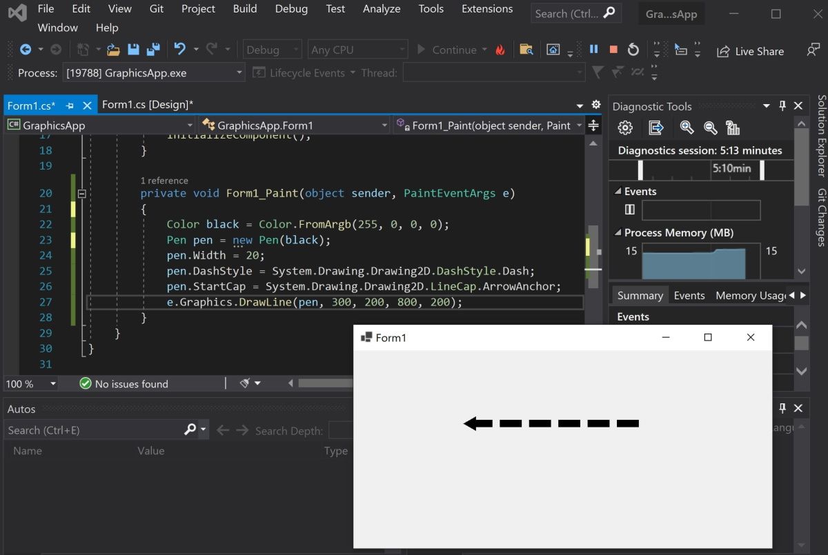
e.Graphics.DrawLine(blackPen, 300, 200, 800, 200); - You can modify the properties for the pen object to change its width, dash style, and start or end cap.
 blackPen.Width = 20;
blackPen.DashStyle = System.Drawing.Drawing2D.DashStyle.Dash;
blackPen.StartCap = System.Drawing.Drawing2D.LineCap.ArrowAnchor;
e.Graphics.DrawLine(blackPen, 300, 200, 800, 200); - Press the green play button at the top of Visual Studio to see the changes.

How to Draw Shapes Such as Rectangles and Circles
You can use the shapes classes for different shapes, or draw shapes manually onto the canvas.
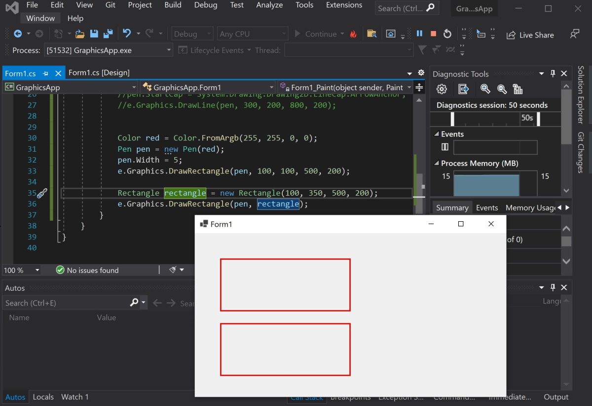
- Create a Color and Pen object as shown in the previous steps. Then, use the DrawRectangle() method to create the rectangle. The arguments are the x and y coordinates for the top-left of the rectangle, along with its width and height.
 Color red = Color.FromArgb(255, 255, 0, 0);
Pen redPen = new Pen(red);
redPen.Width = 5;
e.Graphics.DrawRectangle(redPen, 100, 100, 500, 200); - You can also create a rectangle using the Rectangle Class. First, create a Rectangle object. The arguments are also the x and y coordinates for the top-left corner, width, and height.
Rectangle rectangle = new Rectangle(100, 350, 500, 200); - Use the DrawRectangle() function to draw the rectangle. Instead of passing the x, y, width, and height like before, you can use the Rectangle object instead.
e.Graphics.DrawRectangle(redPen, rectangle); - Press the green play button at the top of Visual Studio to see the changes.

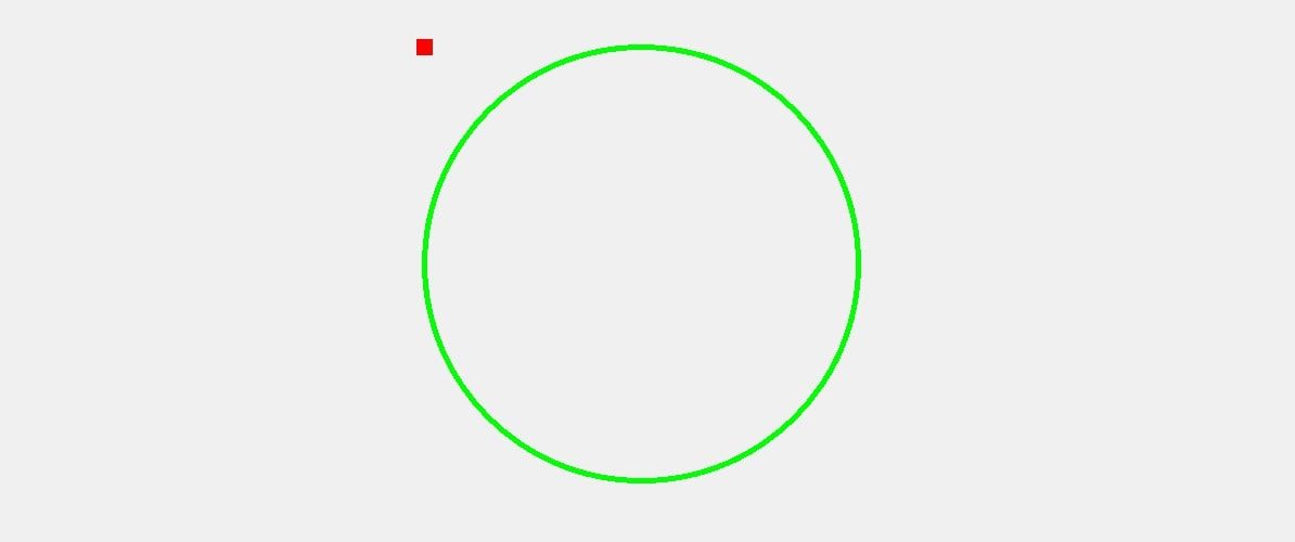
- Go back to the code to draw other shapes. Use the DrawEllipse() function to draw a circle.
 Color green = Color.FromArgb(255, 0, 255, 0);
Pen greenPen = new Pen(green);
greenPen.Width = 5;
e.Graphics.DrawEllipse(greenPen, 400, 150, 400, 400);
When you draw a circle, the x and y coordinates (x=400, y=150) refer to the top-left corner of the circle, not the center of the circle.

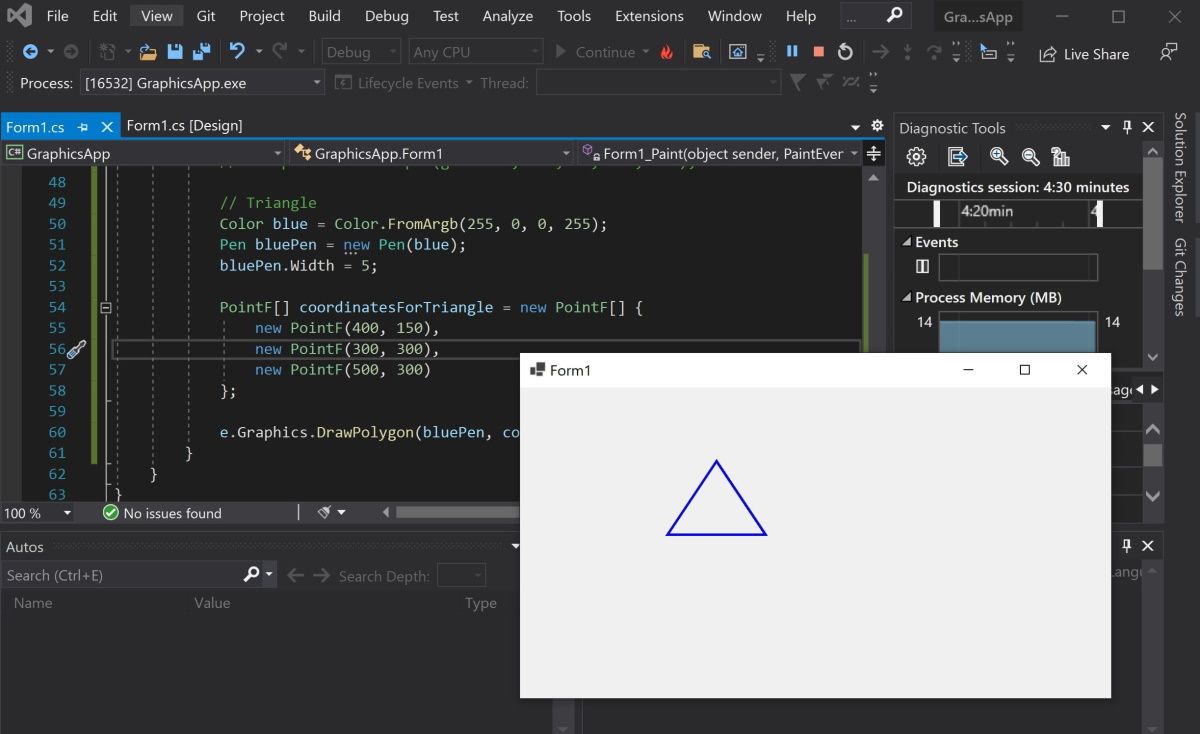
- To draw other shapes such as triangles or hexagons, use the DrawPolygon() method. Here you can specify a list of coordinates to represent the points of the shape.
 Color blue = Color.FromArgb(255, 0, 0, 255);
Pen bluePen = new Pen(blue);
bluePen.Width = 5;PointF[] coordinatesForTriangle = new PointF[] {
    new PointF(400, 150),
    new PointF(300, 300),
    new PointF(500, 300)
};e.Graphics.DrawPolygon(bluePen, coordinatesForTriangle);
The DrawPolygon() method will draw lines between the points specified.

How to Use the Brush Class to Fill In Shapes With Color
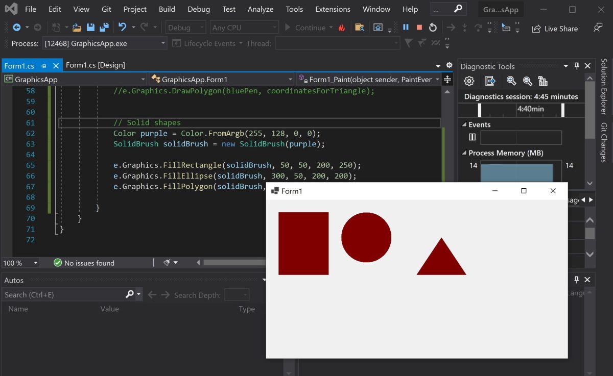
You can use the FillRectangle(), FillEllipses() or FillTriangle() methods to create shapes with a solid color.
- First, create a brush object.
 Color purple = Color.FromArgb(255, 128, 0, 0);
SolidBrush solidBrush = new SolidBrush(purple); - Use the FillRectangle(), FillEllipses() or FillTriangle() methods. They work the same way as the draw functions above, except instead of a Pen, they use a Brush object.
 e.Graphics.FillRectangle(solidBrush, 50, 50, 200, 250);
e.Graphics.FillEllipse(solidBrush, 300, 50, 200, 200);
e.Graphics.FillPolygon(solidBrush, new PointF[] { new PointF(700, 150), new PointF(600, 300), new PointF(800, 300) });
- You can also input a shape object directly instead of providing coordinates.
 Rectangle rectangle = new Rectangle(100, 350, 500, 200);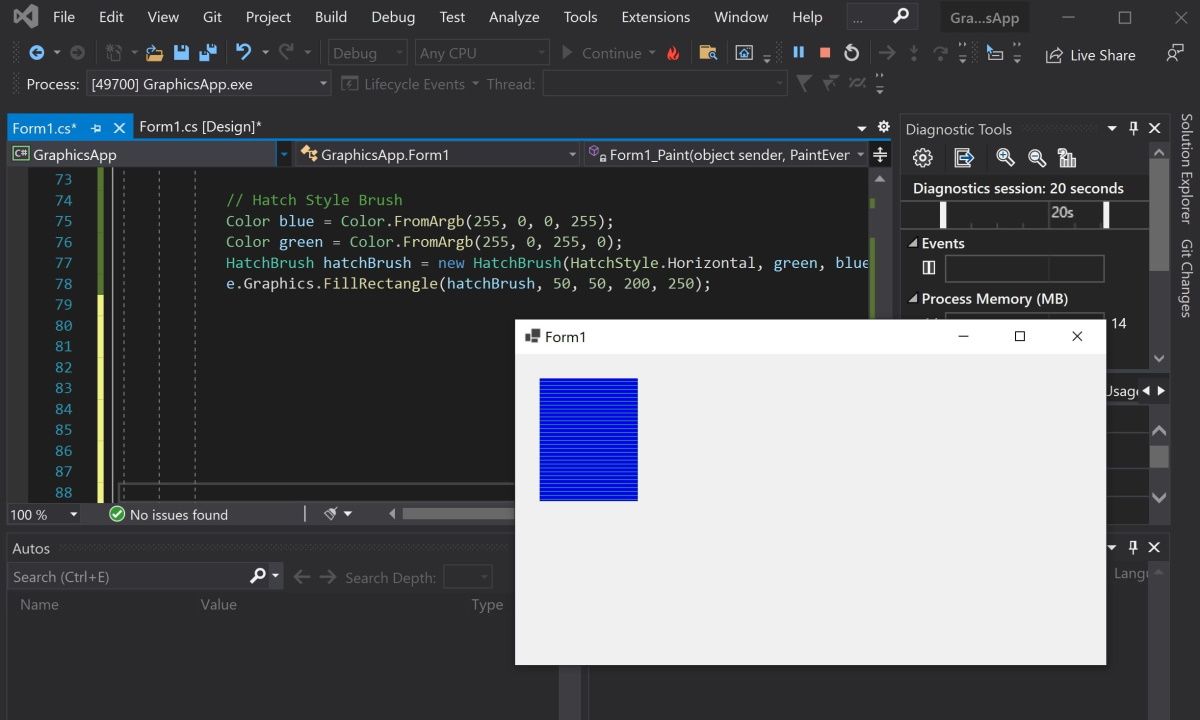
e.Graphics.FillRectangle(solidBrush, rectangle); - Use the HatchBrush to fill the shape using a different fill style, such as a horizontal or vertical pattern.
 Color blue = Color.FromArgb(255, 0, 0, 255);
Color green = Color.FromArgb(255, 0, 255, 0);
HatchBrush hatchBrush = new HatchBrush(HatchStyle.Horizontal, green, blue);
e.Graphics.FillRectangle(hatchBrush, 50, 50, 200, 250);
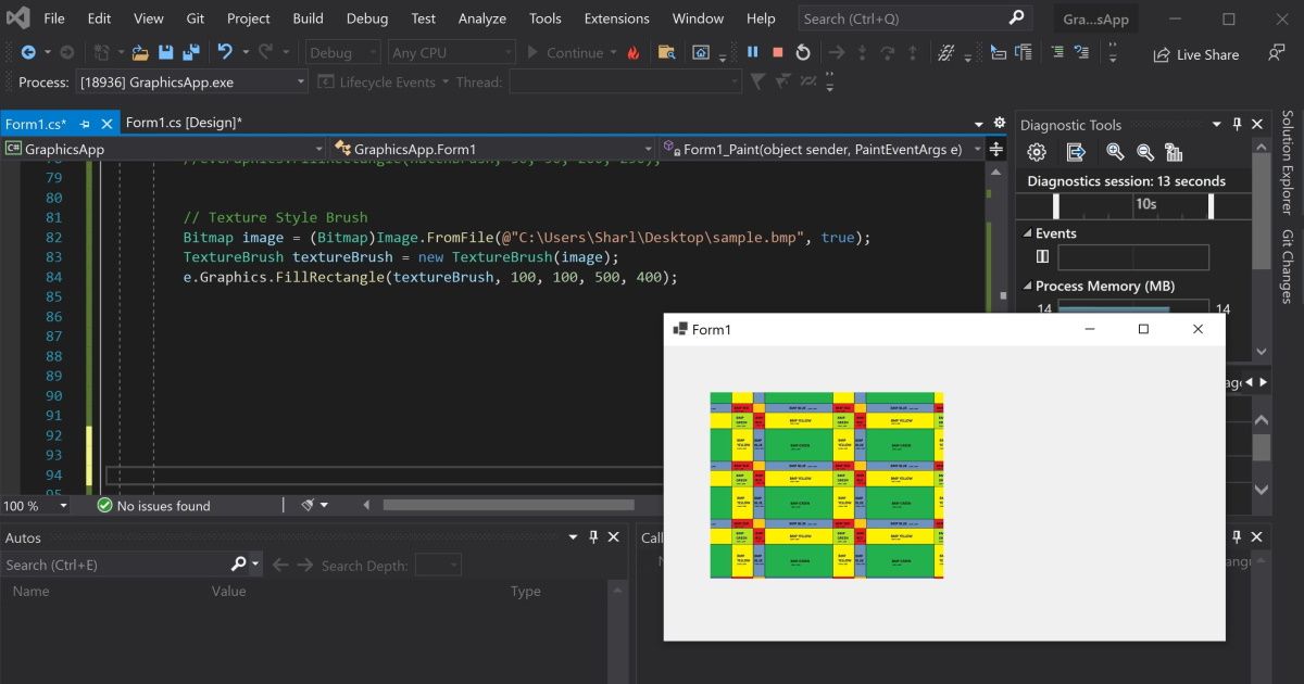
- You can use the TextureBrush to fill a shape using an image. Here, create a bitmap by pointing to an image file. Instead of creating a brush using a color, create it using the image.
 Bitmap image = (Bitmap)Image.FromFile(@"C:UsersSharlDesktopflag.bmp", true);
TextureBrush textureBrush = new TextureBrush(image);
e.Graphics.FillRectangle(textureBrush, 100, 100, 500, 400);
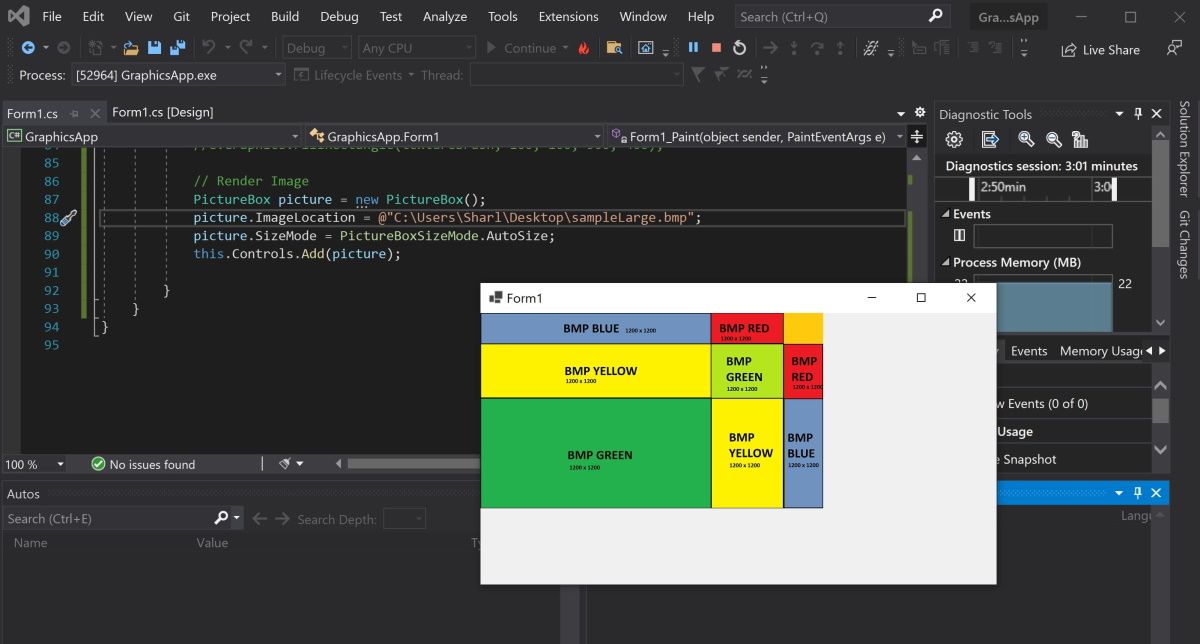
How to Render Images Onto the Form
To render an image, create a PictureBox control object and add it to the form.
- Create a PictureBox control object using an image file.
 PictureBox picture = new PictureBox();
picture.ImageLocation = @"C:UsersSharlDesktopflagLarge.bmp"; - Set the size of the image and add it onto the form so it renders.
 picture.SizeMode = PictureBoxSizeMode.AutoSize;
this.Controls.Add(picture); - Press the green start button at the top to view the image.

Adding More Shapes to Your Windows Form
You should now understand how to add lines, shapes, and images to your Windows form. You can combine shapes to create new shapes. You can also play around with the built-in functions to create more complex shapes.
See how you can draw shapes, use colors, and render images in a WinForms app.
Windows Forms is a framework that lets you build desktop applications. You can click and drag components like buttons onto a visual user interface. It also helps you manually create various shapes within your code.
This article will show you how to add lines, shapes, and images to your application. This tutorial uses the Visual Studio 2019 Community Edition to show examples.
What Are the Built-In Classes Used for Drawing Graphics?
Windows Forms uses the C# programming language. Its built-in classes and methods allow you to draw various shapes onto a Windows Form canvas. These include the Graphics, Pen, Color, and Brush classes.
|
Class |
Description |
|---|---|
|
Graphics |
The Graphics class allows you to draw shapes and lines onto the canvas. It includes methods such as:
|
|
Pen |
The Pen class allows you to specify the properties of a ‘pen’ tip which you can use to draw your shapes. You can specify properties such as color, thickness, or dash style. Methods include:
|
|
Color |
A color object made up of R (red), G (green), and B (blue) values. You will need a color object for many of the built-in methods that create shapes. |
|
SolidBrush, HatchBrush, TextureBrush |
These brush classes derive from the «Brush» interface. These classes allow you to color in blank spaces on the canvas. You can also choose to fill the spaces using different patterns or textures. You can specify properties such as the color. |
|
Rectangle, Line, Polygon, Ellipse |
You can create objects based on these shapes, and use them when calling methods such as DrawRectangle(). Instead of passing the x, y, width, and height as arguments, you can choose to pass an existing Rectangle object instead. |
To view the source code for a running example of the above tutorial, visit the GitHub repository. You can try out the following examples once you’ve created a Winforms application.
How to Add a Paint on Form Load Event Handler
First, add an event handler to draw shapes when the canvas loads.
- Add a Paint function for the form.
 private void Form1_Paint(object sender, PaintEventArgs e)
{
    // Code goes here
} - Go into the Design View Tab.
- In the Properties window, select the lightning icon to open the «Events» tab.
- In «Paint», under «Appearance», select the Form1_Paint function. This will execute the function when you run the application.
How to Draw Lines Onto a Windows Form Canvas
You can use a Color, Pen, and the DrawLine() method to draw lines on a canvas.
- Inside the Form1_Paint() function, create a Color object with the color you want the line to be. Then, create a Pen object to draw the line with.
 Color black = Color.FromArgb(255, 0, 0, 0);
Pen blackPen = new Pen(black); - The DrawLine() method from the Graphics class will draw a line using the pen. This will start drawing a line from an x, y position to another x, y position.
e.Graphics.DrawLine(blackPen, 300, 200, 800, 200); - You can modify the properties for the pen object to change its width, dash style, and start or end cap.
 blackPen.Width = 20;
blackPen.DashStyle = System.Drawing.Drawing2D.DashStyle.Dash;
blackPen.StartCap = System.Drawing.Drawing2D.LineCap.ArrowAnchor;
e.Graphics.DrawLine(blackPen, 300, 200, 800, 200); - Press the green play button at the top of Visual Studio to see the changes.
How to Draw Shapes Such as Rectangles and Circles
You can use the shapes classes for different shapes, or draw shapes manually onto the canvas.
- Create a Color and Pen object as shown in the previous steps. Then, use the DrawRectangle() method to create the rectangle. The arguments are the x and y coordinates for the top-left of the rectangle, along with its width and height.
 Color red = Color.FromArgb(255, 255, 0, 0);
Pen redPen = new Pen(red);
redPen.Width = 5;
e.Graphics.DrawRectangle(redPen, 100, 100, 500, 200); - You can also create a rectangle using the Rectangle Class. First, create a Rectangle object. The arguments are also the x and y coordinates for the top-left corner, width, and height.
Rectangle rectangle = new Rectangle(100, 350, 500, 200); - Use the DrawRectangle() function to draw the rectangle. Instead of passing the x, y, width, and height like before, you can use the Rectangle object instead.
e.Graphics.DrawRectangle(redPen, rectangle); - Press the green play button at the top of Visual Studio to see the changes.
- Go back to the code to draw other shapes. Use the DrawEllipse() function to draw a circle.
 Color green = Color.FromArgb(255, 0, 255, 0);
Pen greenPen = new Pen(green);
greenPen.Width = 5;
e.Graphics.DrawEllipse(greenPen, 400, 150, 400, 400);
When you draw a circle, the x and y coordinates (x=400, y=150) refer to the top-left corner of the circle, not the center of the circle.
- To draw other shapes such as triangles or hexagons, use the DrawPolygon() method. Here you can specify a list of coordinates to represent the points of the shape.
 Color blue = Color.FromArgb(255, 0, 0, 255);
Pen bluePen = new Pen(blue);
bluePen.Width = 5;PointF[] coordinatesForTriangle = new PointF[] {
    new PointF(400, 150),
    new PointF(300, 300),
    new PointF(500, 300)
};e.Graphics.DrawPolygon(bluePen, coordinatesForTriangle);
The DrawPolygon() method will draw lines between the points specified.
How to Use the Brush Class to Fill In Shapes With Color
You can use the FillRectangle(), FillEllipses() or FillTriangle() methods to create shapes with a solid color.
- First, create a brush object.
 Color purple = Color.FromArgb(255, 128, 0, 0);
SolidBrush solidBrush = new SolidBrush(purple); - Use the FillRectangle(), FillEllipses() or FillTriangle() methods. They work the same way as the draw functions above, except instead of a Pen, they use a Brush object.
 e.Graphics.FillRectangle(solidBrush, 50, 50, 200, 250);
e.Graphics.FillEllipse(solidBrush, 300, 50, 200, 200);
e.Graphics.FillPolygon(solidBrush, new PointF[] { new PointF(700, 150), new PointF(600, 300), new PointF(800, 300) }); - You can also input a shape object directly instead of providing coordinates.
 Rectangle rectangle = new Rectangle(100, 350, 500, 200);
e.Graphics.FillRectangle(solidBrush, rectangle); - Use the HatchBrush to fill the shape using a different fill style, such as a horizontal or vertical pattern.
 Color blue = Color.FromArgb(255, 0, 0, 255);
Color green = Color.FromArgb(255, 0, 255, 0);
HatchBrush hatchBrush = new HatchBrush(HatchStyle.Horizontal, green, blue);
e.Graphics.FillRectangle(hatchBrush, 50, 50, 200, 250); - You can use the TextureBrush to fill a shape using an image. Here, create a bitmap by pointing to an image file. Instead of creating a brush using a color, create it using the image.
 Bitmap image = (Bitmap)Image.FromFile(@"C:UsersSharlDesktopflag.bmp", true);
TextureBrush textureBrush = new TextureBrush(image);
e.Graphics.FillRectangle(textureBrush, 100, 100, 500, 400);
How to Render Images Onto the Form
To render an image, create a PictureBox control object and add it to the form.
- Create a PictureBox control object using an image file.
 PictureBox picture = new PictureBox();
picture.ImageLocation = @"C:UsersSharlDesktopflagLarge.bmp"; - Set the size of the image and add it onto the form so it renders.
 picture.SizeMode = PictureBoxSizeMode.AutoSize;
this.Controls.Add(picture); - Press the green start button at the top to view the image.
Adding More Shapes to Your Windows Form
You should now understand how to add lines, shapes, and images to your Windows form. You can combine shapes to create new shapes. You can also play around with the built-in functions to create more complex shapes.
Introduction
GDI+ consists of the set of .NET base classes that are available to control custom drawing on the screen. These classes arrange for the appropriate instructions to be sent to the graphics device drivers to ensure the correct output is placed on the screen. GDI provides a level of abstraction, hiding the differences between different video cards. You simply call on the Windows API function to do the specific task, and internally the GDI figures out how to get the client’s particular video card to do whatever it is you want when they run your particular piece of code.
Not only this, but the client has several display devices — for example — monitors and printers — GDI achieves the task of making the printer look the same onscreen as far as the application is concerned. If the client wants to print something instead of displaying it, your application will simply inform the system that the output device is the printer and then call the same API functions in exactly the same way. As you can see, the device-context (DC) object is a very powerful mechanism. Having said that, we can also use this layer of abstraction to draw onto a Windows Form. This paper will therefore begin with an example of a basic Windows Forms development in order to demonstrate how to draw graphics onto a Windows Form, or a control on that form. The focus of this article will be on graphics.
The Form object is used to represent any Window in your application. When creating a main window, you must follow two mandatory steps:
- Derive a new custom class from System.Windows.Forms.Form
- Configure the application’s Main() method to call System.Windows.Forms.Application.Run(), passing an instance of your new Form derived as a class argument.
Here is an example:
C# File: MyForm.cs
using System;
using System.Windows.Forms;
public class MyForm : System.Windows.Forms.Form
{
    public MyForm()
    {
        Text = "No Graphics";
    }
    public static void Main()
    {
        Application.Run(new MyForm());
    }
}
To compile:
C:WindowsMicrosoft.NETFrameworkv2.050727>csc /target:winexe MyForm.cs
So now we have a blank form. So what do we do to learn how to use graphics? If you use Visual Studio 2005 you probably know that the .NET Framework 2.0 supports partial classes. With Visual Studio 2005, a Windows Form is completely defined with a single C# source file. The code generated by the IDE was separated from your code by using regions, therefore taking advantage of partial classes.
By default, each form named Form111 corresponds to two files; Form111.cs which contains your code and Form111.Designer.cs, which contains the code generated by the IDE. The code, however, is usually generated by dragging and dropping controls. One of the simplest uses for the System.Drawing namespace is specifying the location of the controls in a Windows Forms application. More to the point, user-defined types are often referred to as structures.
To draw lines and shapes you must follow these steps:
-
Create a Graphics object by calling System.Windows.Forms.Control.CreateGraphics method. The Graphics object contains the Windows DC you need to draw with. The device control created is associated with the display device, and also with the Window.
-
Create a Pen object
-
Call a member of the Graphics class to draw on the control using the Pen
Here is an example of a Form with a line drawn at a 60 degree angle from the upper-most left hand corner:
//File: DrawLine.cs
using System;
using System.Drawing;
using System.Drawing.Drawing2D;
using System.Collections;
using System.ComponentModel;
using System.Windows.Forms;
using System.Data;
public class MainForm : System.Windows.Forms.Form
{
    private System.ComponentModel.Container components;
    public MainForm()
    {
        InitializeComponent();
        CenterToScreen();
        SetStyle(ControlStyles.ResizeRedraw, true);
    }
    //  Clean up any resources being used.
    protected override void Dispose(bool disposing)
    {
        if (disposing)
        {
            if (components != null)
            {
                components.Dispose();
            }
        }
        base.Dispose(disposing);
    }
    #region Windows Form Designer generated code
    private void InitializeComponent()
    {
        this.AutoScaleBaseSize = new System.Drawing.Size(5, 13);
        this.ClientSize = new System.Drawing.Size(292, 273);
        this.Text = "Fun with graphics";
        this.Resize += new System.EventHandler(this.Form1_Resize);
        this.Paint += new System.Windows.Forms.PaintEventHandler(this.MainForm_Paint);
    }
    #endregion
    [STAThread]
    static void Main()
    {
        Application.Run(new MainForm());
    }
    private void MainForm_Paint(object sender, System.Windows.Forms.PaintEventArgs e)
    {
        //create a graphics object from the form
        Graphics g = this.CreateGraphics();
        // create  a  pen object with which to draw
        Pen p = new Pen(Color.Red, 7);  // draw the line
        // call a member of the graphics class
        g.DrawLine(p, 1, 1, 100, 100);
    }
    private void Form1_Resize(object sender, System.EventArgs e)
    {
        // Invalidate();  See ctor!
    }
}
TO COMPILE:
csc.exe /target:winexe DrawLine.cs
Typically, you specify the Pen class color and width in pixels with the constructor. The code above draws a 7-pixel wide red line from the upper-left corner (1,1,) to a point near the middle of the form (100, 100). Note the following code that draws a pie shape:
//File: DrawPie.cs
using System;
using System.Drawing;
using System.Drawing.Drawing2D;
using System.Collections;
using System.ComponentModel;
using System.Windows.Forms;
using System.Data;
public class MainForm : System.Windows.Forms.Form
{
    private System.ComponentModel.Container components;
    public MainForm()
    {
        InitializeComponent();
        CenterToScreen();
        SetStyle(ControlStyles.ResizeRedraw, true);
    }
    protected override void Dispose(bool disposing)
    {
        if (disposing)
        {
            if (components != null)
            {
                components.Dispose();
            }
        }
        base.Dispose(disposing);
    }
    #region Windows Form Designer generated code
    //
    private void InitializeComponent()
    {
        this.AutoScaleBaseSize = new System.Drawing.Size(5, 13);
        this.ClientSize = new System.Drawing.Size(292, 273);
        this.Text = "Fun with graphics";
        this.Resize += new System.EventHandler(this.Form1_Resize);
        this.Paint += new System.Windows.Forms.PaintEventHandler(this.MainForm_Paint);
    }
    #endregion
    [STAThread]
    static void Main()
    {
        Application.Run(new MainForm());
    }
    private void MainForm_Paint(object sender, System.Windows.Forms.PaintEventArgs e)
    {
        //create a graphics object from the form
        Graphics g = this.CreateGraphics();
        Pen p = new Pen(Color.Blue, 3);
        g.DrawPie(p, 1, 1, 100, 100, -30, 60);
    }
    private void Form1_Resize(object sender, System.EventArgs e)
    {
    }
}
To compile:
csc.exe /target:winexe DrawPie.cs
A structure, or «struct», is a cut-down class that does almost everything a class does, except support inheritance and finalizers. A structure is a composite of other types that make easier to work with related data. The simplest example is System.Drawing.Point, which contain X and Y integer properties that define the horizontal and vertical coordinates of a point.
The Point structure simplifies working with coordinates by providing constructors and members as follows:
// Requires reference to System.Drawing
// Create point
System.Drawing.Point p = new System.Drawing.Point(20, 20);
// move point diagonally
p.Offset(-1, -1)
Console.WriteLine("Point X {0}, Y {1}", p.X, p.Y.);
So as the coordinates of a point define its location, this process also specifies a control’s location. Just create a new Point structure by specifying the coordinates relative to the upper-left corner of the form, and use the Point to set the control’s Location property.
Graphics.DrawLines, Graphics.DrawPolygons, and Graphics.DrawRectangles accept arrays as parameters to help you draw more complex shapes:
Here is an example of a polygon, but with its contents filled. Notice the code responsible for filling the shape:
DrawPolygonAndFill.cs
using System;
using System.Drawing;
using System.Drawing.Drawing2D;
using System.Collections;
using System.ComponentModel;
using System.Windows.Forms;
using System.Data;
public class MainForm : System.Windows.Forms.Form
{
    private System.ComponentModel.Container components;
    public MainForm()
    {
        InitializeComponent();
        CenterToScreen();
        SetStyle(ControlStyles.ResizeRedraw, true);
    }
    protected override void Dispose(bool disposing)
    {
        if (disposing)
        {
            if (components != null)
            {
                components.Dispose();
            }
        }
        base.Dispose(disposing);
    }
    #region Windows Form Designer generated code
    private void InitializeComponent()
    {
        this.AutoScaleBaseSize = new System.Drawing.Size(5, 13);
        this.ClientSize = new System.Drawing.Size(292, 273);
        this.Text = "Fun with graphics";
        this.Resize += new System.EventHandler(this.Form1_Resize);
        this.Paint += new System.Windows.Forms.PaintEventHandler(this.MainForm_Paint);
    }
    #endregion
    [STAThread]
    static void Main()
    {
        Application.Run(new MainForm());
    }
    private void MainForm_Paint(object sender, System.Windows.Forms.PaintEventArgs e)
    {
        //create a graphics object from the form
        Graphics g = this.CreateGraphics();
        Brush b = new SolidBrush(Color.Maroon);
        Point[] points = new Point[]
        {
            new Point(10, 10),
            new Point(10, 100),
            new Point(50, 65),
            new Point(100, 100),
            new Point(85, 40)};   // Notice the braces, as used in structures
            g.FillPolygon(b, points);
        }
    }
    private void Form1_Resize(object sender, System.EventArgs e)
    {
    }
}
Customizing Pens
The color and size of a pen is specified in the Pen constructor, so you can manipulate the pattern and the endcaps. The endcaps are the end of the line, and you can use them to create arrows and other special effects. While pens by default draw straight lines, their properties can be set to one of these values: DashStyle.Dash, DashStyle.DashDot, DashStyle.DashDotDot, DashStyle.Dot, or DashStyle.Solid. Consider this final example:
UsePen.cs
using System;
using System.Drawing;
using System.Drawing.Drawing2D;
using System.Collections;
using System.ComponentModel;
using System.Windows.Forms;
using System.Data;
public class MainForm : System.Windows.Forms.Form
{
    private System.ComponentModel.Container components;
    public MainForm()
    {
        InitializeComponent();
        CenterToScreen();
        SetStyle(ControlStyles.ResizeRedraw, true);
    }
    //  Clean up any resources being used.
    protected override void Dispose(bool disposing)
    {
        if (disposing)
        {
            if (components != null)
            {
                components.Dispose();
            }
        }
        base.Dispose(disposing);
    }
    #region Windows Form Designer generated code
    private void InitializeComponent()
    {
        this.AutoScaleBaseSize = new System.Drawing.Size(5, 13);
        this.ClientSize = new System.Drawing.Size(292, 273);
        this.Text = "Learning graphics";
        this.Resize += new System.EventHandler(this.Form1_Resize);
        this.Paint += new System.Windows.Forms.PaintEventHandler(this.MainForm_Paint);
    }
    #endregion
    [STAThread]
    static void Main()
    {
        Application.Run(new MainForm());
    }
    private void MainForm_Paint(object sender, System.Windows.Forms.PaintEventArgs e)
    {
        //create a graphics object from the form
        Graphics g = this.CreateGraphics();
        // create a Pen object
        Pen p = new Pen(Color.Red, 10);
        p.StartCap = LineCap.ArrowAnchor;
        p.EndCap = LineCap.DiamondAnchor;
        g.DrawLine(p, 50, 25, 400, 25);
        p.StartCap = LineCap.SquareAnchor;
        p.EndCap = LineCap.Triangle;
        g.DrawLine(p, 50, 50, 400, 50);
        p.StartCap = LineCap.Flat;
        p.EndCap = LineCap.Round;
        g.DrawLine(p, 50, 75, 400, 75);
        p.StartCap = LineCap.RoundAnchor;
        p.EndCap = LineCap.Square;
        g.DrawLine(p, 50, 100, 400, 100);
    }
    private void Form1_Resize(object sender, System.EventArgs e)
    {
        // Invalidate();  See ctor!
    }
}
The basics underlying principles in this paper indicate the location and size of points so that they for a line or a shape. This should the new developer to understand that these principles can be expanded upon to specify the size and location of controls that are dragged and dropped onto a Windows Form. For instance, if we were to start Visual Studio 2005 and begin a Forms application, we could set that Form background color to white. The designer file and the source file that comprise the application would both reflect that property: the setting of the property would cause the IDE to generate the code in the Form.Designer.cs file. Well, that all for now.
DrawLine.cs
using System;
using System.Drawing;
using System.Drawing.Drawing2D;
using System.Collections;
using System.ComponentModel;
using System.Windows.Forms;
using System.Data;
public class MainForm : System.Windows.Forms.Form
{
    private System.ComponentModel.Container components;
    public MainForm()
    {
        InitializeComponent();
        CenterToScreen();
        SetStyle(ControlStyles.ResizeRedraw, true);
    }
    //  Clean up any resources being used.
    protected override void Dispose(bool disposing)
    {
        if (disposing)
        {
            if (components != null)
            {
                components.Dispose();
            }
        }
        base.Dispose(disposing);
    }
    #region Windows Form Designer generated code
    private void InitializeComponent()
    {
        this.AutoScaleBaseSize = new System.Drawing.Size(5, 13);
        this.ClientSize = new System.Drawing.Size(292, 273);
        this.Text = "Learning graphics";
        this.Resize += new System.EventHandler(this.Form1_Resize);
        this.Paint += new System.Windows.Forms.PaintEventHandler(this.MainForm_Paint);
    }
    #endregion
    [STAThread]
    static void Main()
    {
        Application.Run(new MainForm());
    }
    private void MainForm_Paint(object sender, System.Windows.Forms.PaintEventArgs e)
    {
        //create a graphics object from the form
        Graphics g = this.CreateGraphics();
        // create  a  pen object with which to draw
        Pen p = new Pen(Color.Red, 7);
        // draw the line
        g.DrawLine(p, 1, 1, 100, 100);
    }
    private void Form1_Resize(object sender, System.EventArgs e)
    {
        // Invalidate();  See ctor!
    }
}Создание графического приложения
Последнее обновление: 13.11.2021
Графический редактор Windows Forms
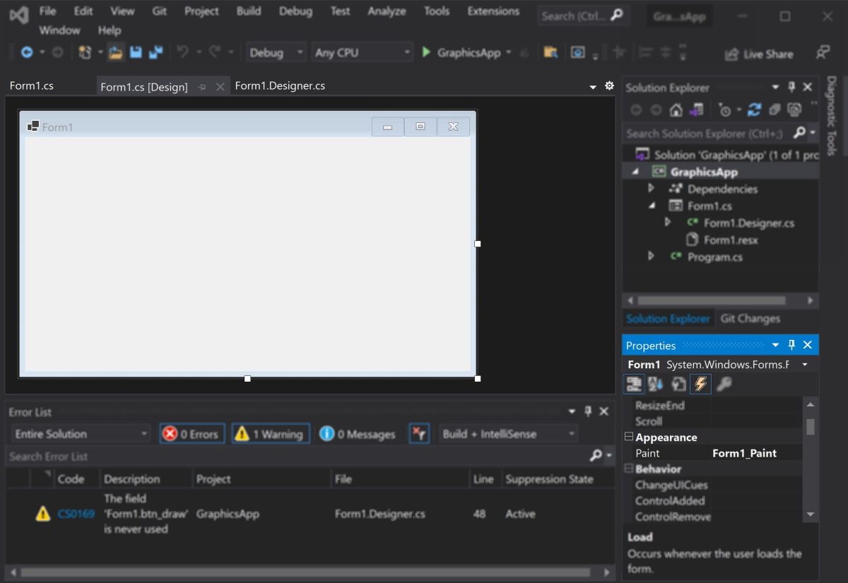
Одним из преимуществ разработки в Visual Studio приложений Windows Forms является наличие графического редактора, который позволяет в графическом виде представить
создаваемую форму и в принципе упрощает работу с графическими компонентами.
Для открытия формы в режиме графического дизайнера нажмем на в структуре проекта на файл Form1.cs либо левой кнопкой мыши двойным кликом,
либо правой кнопкой мыши и в появившемся контекстном меню выберем View Designer (также можно использовать комбинацию клавиш Shift+F7)
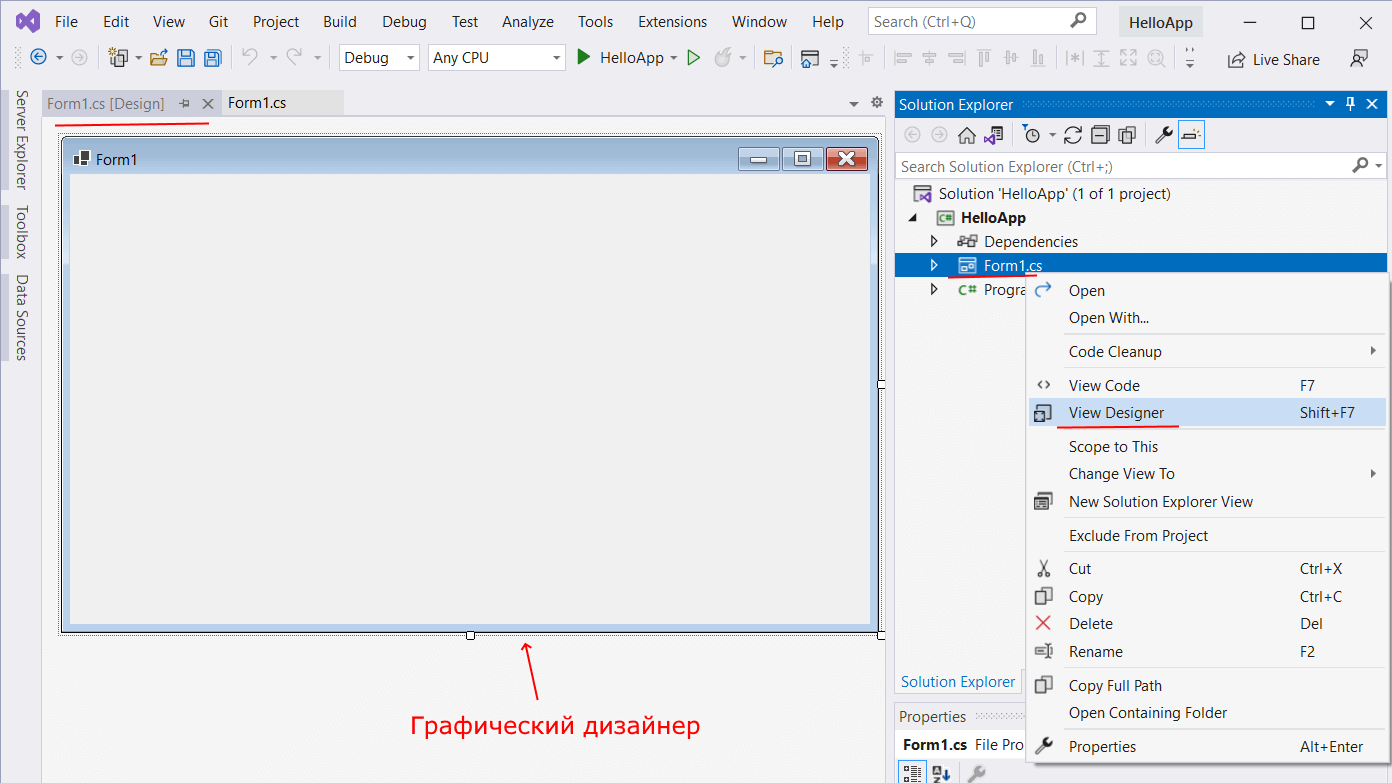
После этого в Visual Studio откроется выбранная форма в графическом виде.
В то же время следует отметить, что на более слабых компьютерах окно дизайнера можно открываться довольно долго, а на некоторых — довольно слабых компьютерах может и вообще не открыться.
При выборе формы в окне дизайнера внизу справа под структурой проекта мы сможем найти окно Properties(Свойства).
Так как у меня в данный момент выбрана форма как элемент управления, то в этом поле отображаются свойства, связанные с формой.
Теперь найдем в этом окне свойство формы Text и изменим его значение на любое другое:
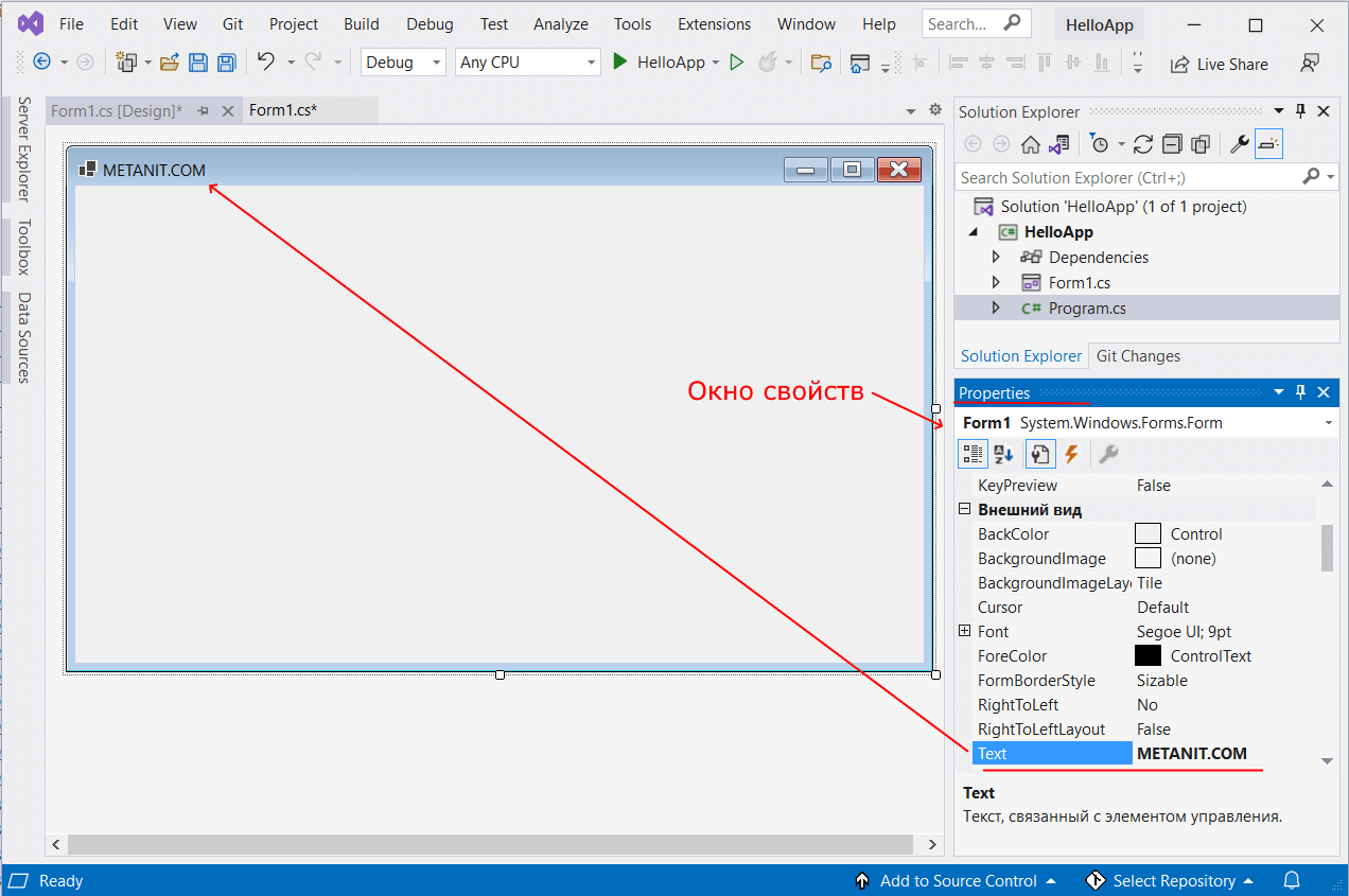
Таким образом мы поменяли заголовок формы. И подобным образом мы можем поменять другие свойства формы, которые доступны в окне свойств.
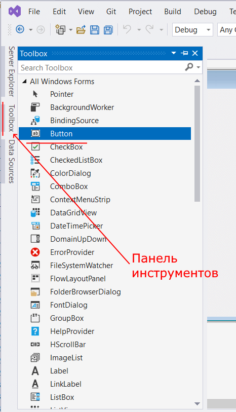
Но Visual Studio имеет еще одну связанную функциональность. Она обладает панелью графических инструментов. И мы можем, вместо создания элементов управления в коде C#,
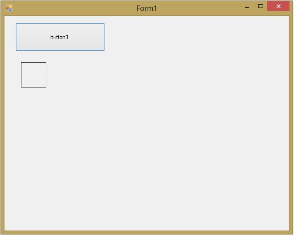
просто переносить их на форму с панели инструментов с помощь мыши. Так, перенесем на форму какой-нибудь элемент управления, например, кнопку. Для этого
найдем в левой части Visual Studio вкладку Toolbox (Панель инструментов). Нажмем на эту вкладку, и у нас откроется панель с элементами,
откуда мы можем с помощью мыши перенести на форму любой элемент:
Найдем среди элементов кнопку и, захватив ее указателем мыши, перенесем на форму:
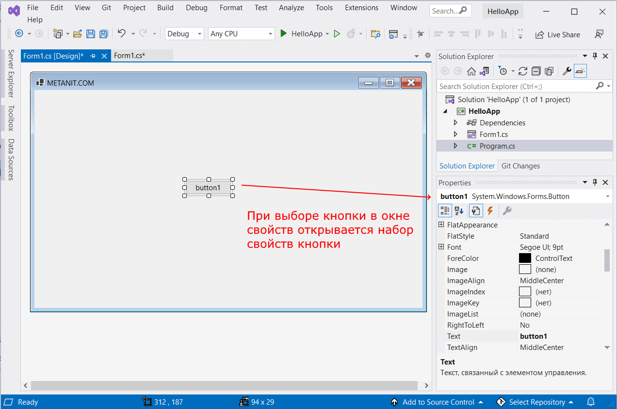
Причем при выборе кнопки она открывается в окне свойств и, как и для всей формы, для кнопки в окне свойств мы можем изменить значения различных свойств.
Кроме того, если после переноса кнопки на форму мы откроем файл Form1.
 namespace HelloApp
{
    partial class Form1
    {
        /// <summary>
        ///  Required designer variable.
        /// </summary>
        private System.ComponentModel.IContainer components = null;

        /// <summary>
        ///  Clean up any resources being used.
        /// </summary>
        /// <param name="disposing">true if managed resources should be disposed; otherwise, false.</param>
        protected override void Dispose(bool disposing)
        {
            if (disposing && (components != null))
            {
                components.Dispose();
            }
            base.Dispose(disposing);
        }

        #region Windows Form Designer generated code

        /// <summary>
        ///  Required method for Designer support - do not modify
        ///  the contents of this method with the code editor.
        /// </summary>
        private void InitializeComponent()
        {
            this.button1 = new System.Windows.Forms.Button();
            this.SuspendLayout();
            //
            // button1
            //
            this.button1.Location = new System.Drawing.Point(312, 187);
            this.button1.Name = "button1";
            this.button1.Size = new System.Drawing.Size(94, 29);
            this.button1.TabIndex = 0;
            this.button1.Text = "button1";
            this.button1.UseVisualStyleBackColor = true;
            //
            // Form1
            //
            this.AutoScaleDimensions = new System.Drawing.SizeF(8F, 20F);
            this.AutoScaleMode = System.Windows.Forms.AutoScaleMode.Font;
            this.ClientSize = new System.Drawing.Size(800, 450);
            this.Controls.Add(this.button1);
            this.Name = "Form1";
            this.Text = "METANIT.COM";
            this.ResumeLayout(false);

        }

        #endregion

        private Button button1;
    }
}
Мы видим, что в класс Form1 была добавлена переменная button1 типа Button и для этой переменной, как и для объекта формы, задан ряд свойств.
И если в окне свойств мы поменяем значения этих свойств, то в этом файле также изменяться их значения. Как в случае с текстом формы:
this.Text = "METANIT.COM";
Это визуальная часть. Теперь приступим к самому программированию. Добавим простейший код на языке C#, который бы выводил сообщение по нажатию кнопки.
Для этого перейдем в файл кода Form1.cs, который связан с этой формой. По умолчанию после создания проекта он имеет код типа следующего:
namespace HelloApp
{
    public partial class Form1 : Form
    {
        public Form1()
        {
            InitializeComponent();
        }
    }
}
Изменим этот код следующим образом:
namespace HelloApp
{
    public partial class Form1 : Form
    {
        public Form1()
        {
            InitializeComponent();

            button1.Click += button1_Click;
        }

        private void button1_Click(object? sender, EventArgs e)
        {
            MessageBox.Show("Привет");
        }
    }
}
Кнопка обладает событием Click, которое генерируется при нажатии. В данном случае в конструкторе формы мы подвязываем к кнопке button1 в качестве обработчика события
нажатия метод button1_Click, в котором с помощью метода MessageBox.Show выводит сообщение. Текст сообщения передается в метод в качестве параметра.
Стоит отметить, что графический дизайнер позволяет автоматически сгенерировать обработчик нажатия кнопки. Для этого надо
в окне дизайнера нажать на кнопку на форме двойным щелчком мыши.
Теперь запустим проект и мы увидим форму с кнопкой, на которую мы можем нажать и получить сообщение:
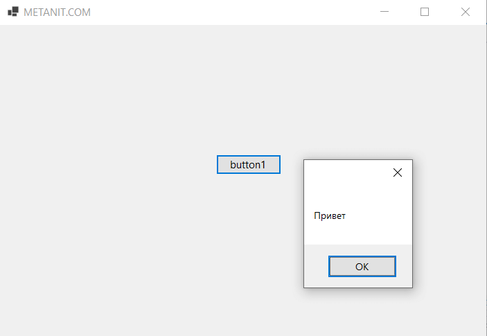
![]()
Лабораторная работа №4
Основы работы с графикой в C# с использованием Windows Forms. Класс Graphics.
1. Цель
ознакомиться с компонентами и методами работы с графикой в С# c использованием Windows Form в простых Windows приложениях. Ознакомится с свойствами и методами класса Graphics.
2.Методические указания
1.При изучении языка программирования С# будет использоваться интегрированная среда разработки программного обеспечения Microsoft Visual Studio Express 2013 для Windows Desktop. Будут использованы основные элементы .NET Framework и связь С# с элементами платформы .NET.
2.По окончанию работы сохраните все созданные файлы на своих носителях.
3.Защита лабораторной работы производится только при наличии электронного варианта работающего скрипта.
3.Теоретические сведения
Пространство имен using System.Drawing обеспечивает доступ к функциональным возможностям графического интерфейса GDI+. Пространства имен
System.Drawing.Drawing2D, System.Drawing.Imaging, и System.Drawing.Text
обеспечивают дополнительные функциональные возможности.
Класс Graphics предоставляет методы рисования на устройстве отображения. Такие классы, как Rectangle и Point, инкапсулируют элементы GDI+. Класс Pen используется для рисования линий и кривых, а классы, производные от абстрактного класса Brush, используются для заливки фигур.
Синтаксис
Свойства
|
Имя |
Описание |
|||||
|
Clip |
Возвращает или задает объект Region, ограничивающий область |
|||||
|
рисования данного объекта Graphics. |
||||||
|
ClipBounds |
Получает |
структуру |
RectangleF, |
которая |
заключает |
в себе |
|
вырезанную область данного объекта Graphics. |
||||||
|
CompositingMode |
Получает |
значение, |
задающее |
порядок |
рисования |
сложных |
|
изображений в данном объекте Graphics. |
||||||
|
CompositingQuality |
Возвращает или задает качество отрисовки составных |
|||||
|
изображений, которые выводятся в данном объекте Graphics. |
||||||
|
DpiX |
Получает горизонтальное разрешение данного объекта Graphics. |
|||||
|
DpiY |
Получает вертикальное разрешение данного объекта Graphics. |
|
InterpolationMode |
Возвращает |
или задает режим |
интерполяции, связанный с |
||
|
данным объектом Graphics. |
|||||
|
IsClipEmpty |
Получает значение, которое указывает, является ли вырезанная |
||||
|
область данного объекта Graphics пустой. |
|||||
|
IsVisibleClipEmpty |
Получает значение, |
которое указывает, является ли |
видимая |
||
|
вырезанная область данного объекта Graphics пустой. |
|||||
|
Возвращает |
или |
задает |
масштабирование |
между |
|
|
PageScale |
универсальными единицами и единицами страницы для данного |
||||
|
объекта Graphics. |
|||||
|
PageUnit |
Возвращает |
или задает единицу |
измерения для координат |
||
|
страницы данного объекта Graphics. |
|||||
|
Возвращает или задает значение, которое задает порядок |
|||||
|
PixelOffsetMode |
смещения пикселей во время отрисовки данного объекта |
||||
|
Graphics. |
|||||
|
Возвращает или задает начало координат при отрисовке данного |
|||||
|
RenderingOrigin |
объекта Graphics для кистей сглаживания цветовых переходов и |
||||
|
штриховки. |
|||||
|
SmoothingMode |
Возвращает |
или задает качество |
отрисовки данного |
объекта |
|
|
Graphics. |
|||||
|
TextContrast |
Возвращает или задает значение коррекции показателя гаммы |
||||
|
для отрисовки текста. |
|||||
|
TextRenderingHint |
Возвращает или задает режим отрисовки текста, связанного с |
||||
|
данным объектом Graphics. |
|||||
|
Transform |
Возвращает или задает копию геометрического универсального |
||||
|
преобразования объекта Graphics. |
|||||
|
VisibleClipBounds |
Получает ограничивающий прямоугольник видимой вырезанной |
||||
|
области данного объекта Graphics. |
|||||
Основные методы
|
Имя |
Описание |
||
|
AddMetafileComment |
Добавляет комментарий к текущему |
объекту |
|
|
Metafile. |
|||
|
Clear |
Очищает всю поверхность рисования и выполняет |
||
|
заливку поверхности указанным цветом фона. |
|||
|
Dispose |
Освобождает все ресурсы, используемые данным |
||
|
объектом Graphics. |
|||
|
DrawArc(Pen, Rectangle, Single, |
Рисует дугу, которая является частью эллипса, |
||
|
Single) |
заданного структурой Rectangle. |
||
|
DrawArc(Pen, RectangleF, Single, |
Рисует дугу, которая является частью |
эллипса, |
|
|
заданного структурой RectangleF. |
|||
|
Single) |
|||
|
DrawArc(Pen, Int32, Int32, Int32, |
Рисует дугу, которая является частью эллипса, |
||
|
Int32, Int32, Int32) |
заданного парой координат, шириной и высотой. |
||
|
DrawArc(Pen, Single, Single, Single, |
Рисует дугу, которая является частью эллипса, |
||
|
Single, Single, Single) |
заданного парой координат, шириной и высотой. |
||
|
DrawBezier(Pen, Point, Point, |
Рисует кривую Безье, определяемую четырьмя |
||
|
Point, Point) |
структурами Point. |
||
|
DrawBezier(Pen, PointF, PointF, |
Рисует сплайн Безье, определяемый |
четырьмя |
|
PointF, PointF) |
структурами PointF. |
||||||||||||
|
DrawBezier(Pen, Single, Single, |
Строит кривую Безье, определяемую четырьмя |
||||||||||||
|
Single, Single, Single, Single, Single, |
упорядоченными парами координат, которые |
||||||||||||
|
Single) |
представляют собой точки. |
||||||||||||
|
DrawBeziers(Pen, Point[]) |
Рисует |
последовательность |
кривых |
Безье |
из |
||||||||
|
массива структур Point. |
|||||||||||||
|
DrawBeziers(Pen, PointF[]) |
Рисует |
последовательность |
кривых |
Безье |
из |
||||||||
|
массива структур PointF. |
|||||||||||||
|
DrawClosedCurve(Pen, Point[]) |
Строит |
замкнутую |
фундаментальную |
кривую, |
|||||||||
|
определяемую массивом структур Point. |
|||||||||||||
|
DrawClosedCurve(Pen, PointF[]) |
Строит |
замкнутую |
фундаментальную |
кривую, |
|||||||||
|
определяемую массивом структур PointF. |
|||||||||||||
|
DrawClosedCurve(Pen, Point[], |
Строит |
замкнутую |
фундаментальную |
кривую, |
|||||||||
|
определяемую |
массивом |
структур |
Point |
с |
|||||||||
|
Single, FillMode) |
|||||||||||||
|
указанным натяжением. |
|||||||||||||
|
DrawClosedCurve(Pen, PointF[], |
Строит |
замкнутую |
фундаментальную |
кривую, |
|||||||||
|
определяемую |
массивом |
структур |
PointF |
с |
|||||||||
|
Single, FillMode) |
|||||||||||||
|
указанным натяжением. |
|||||||||||||
|
DrawCurve(Pen, Point[]) |
Строит |
фундаментальную |
кривую |
через |
точки |
||||||||
|
указанного массива структур Point. |
|||||||||||||
|
DrawCurve(Pen, PointF[]) |
Строит |
фундаментальную |
кривую |
через |
точки |
||||||||
|
указанного массива структур PointF. |
|||||||||||||
|
Строит фундаментальную кривую через точки |
|||||||||||||
|
DrawCurve(Pen, Point[], Single) |
указанного массива структур Point с указанным |
||||||||||||
|
натяжением. |
|||||||||||||
|
Строит фундаментальную кривую через точки |
|||||||||||||
|
DrawCurve(Pen, PointF[], Single) |
указанного массива структур PointF с указанным |
||||||||||||
|
натяжением. |
|||||||||||||
|
DrawCurve(Pen, PointF[], Int32, |
Строит |
фундаментальную |
кривую |
через |
точки |
||||||||
|
указанного массива структур PointF. Смещение при |
|||||||||||||
|
Int32) |
|||||||||||||
|
рисовании начинается от начала массива. |
|||||||||||||
|
DrawCurve(Pen, Point[], Int32, |
Строит |
фундаментальную |
кривую |
через |
точки |
||||||||
|
указанного |
массива |
структур |
Point |
с указанным |
|||||||||
|
Int32, Single) |
|||||||||||||
|
натяжением. |
|||||||||||||
|
Строит фундаментальную кривую через точки |
|||||||||||||
|
DrawCurve(Pen, PointF[], Int32, |
указанного массива структур PointF с указанным |
||||||||||||
|
Int32, Single) |
натяжением. Смещение при рисовании начинается |
||||||||||||
|
от начала массива. |
|||||||||||||
|
Рисует эллипс, определяемый ограничивающей |
|||||||||||||
|
DrawEllipse(Pen, Rectangle) |
структурой Rectangle. |
||||||||||||
|
DrawEllipse(Pen, RectangleF) |
Рисует |
эллипс, |
определяемый |
ограничивающей |
|||||||||
|
структурой RectangleF. |
|||||||||||||
|
Рисует эллипс, определяемый ограничивающим |
|||||||||||||
|
DrawEllipse(Pen, Int32, Int32, |
прямоугольником, |
заданным |
с |
помощью |
|||||||||
|
Int32, Int32) |
координат |
для |
верхнего |
левого |
угла |
||||||||
|
прямоугольника, высоты и ширины. |
|||||||||||||
|
DrawEllipse(Pen, Single, Single, |
Рисует |
эллипс, |
определенный |
ограничивающим |
|
Single, Single) |
прямоугольником, заданным с помощью пары |
||||||||
|
координат, ширины и высоты. |
|||||||||
|
Формирует |
изображение, |
представленное |
|||||||
|
DrawIcon(Icon, Rectangle) |
указанным объектом Icon в пределах области, |
||||||||
|
заданной структурой Rectangle. |
|||||||||
|
Формирует |
изображение, |
представленное |
|||||||
|
DrawIcon(Icon, Int32, Int32) |
указанным объектом Icon, расположенным по |
||||||||
|
указанным координатам. |
|||||||||
|
Формирует |
изображение, |
представленное |
|||||||
|
DrawIconUnstretched |
указанным |
объектом |
Icon |
без |
его |
||||
|
масштабирования. |
|||||||||
|
DrawLine(Pen, Point, Point) |
Проводит |
линию, |
соединяющую |
две |
структуры |
||||
|
Point. |
|||||||||
|
DrawLine(Pen, PointF, PointF) |
Проводит |
линию, |
соединяющую |
две |
структуры |
||||
|
PointF. |
|||||||||
|
DrawLine(Pen, Int32, Int32, Int32, |
Проводит линию, соединяющую две точки, |
||||||||
|
Int32) |
задаваемые парами координат. |
||||||||
|
DrawLine(Pen, Single, Single, |
Проводит линию, соединяющую две точки, |
||||||||
|
Single, Single) |
задаваемые парами координат. |
||||||||
|
DrawLines(Pen, Point[]) |
Рисует набор сегментов линий, которые соединяют |
||||||||
|
массив структур Point. |
|||||||||
|
DrawLines(Pen, PointF[]) |
Рисует набор сегментов линий, которые соединяют |
||||||||
|
массив структур PointF. |
|||||||||
|
DrawPath |
Рисует объект GraphicsPath. |
||||||||
|
DrawPie(Pen, Rectangle, Single, |
Рисует |
сектор, |
который |
определяется |
эллипсом, |
||||
|
заданным |
структурой |
Rectangle |
и |
двумя |
|||||
|
Single) |
|||||||||
|
радиальными линиями. |
|||||||||
|
DrawPie(Pen, RectangleF, Single, |
Рисует сектор, определяемый эллипсом, заданным |
||||||||
|
структурой |
RectangleF |
и двумя радиальными |
|||||||
|
Single) |
|||||||||
|
линиями. |
|||||||||
|
DrawPie(Pen, Int32, Int32, Int32, |
Рисует сектор, определяемый эллипсом, который |
||||||||
|
задан парой координат, шириной, высотой и двумя |
|||||||||
|
Int32, Int32, Int32) |
|||||||||
|
радиальными линиями. |
|||||||||
|
DrawPie(Pen, Single, Single, Single, |
Рисует сектор, определяемый эллипсом, который |
||||||||
|
задан парой координат, шириной, высотой и двумя |
|||||||||
|
Single, Single, Single) |
|||||||||
|
радиальными линиями. |
|||||||||
|
DrawPolygon(Pen, Point[]) |
Рисует |
многоугольник, определяемый |
массивом |
||||||
|
структур Point. |
|||||||||
|
Рисует многоугольник, определяемый массивом |
|||||||||
|
DrawPolygon(Pen, PointF[]) |
структур PointF. |
||||||||
|
DrawRectangle(Pen, Rectangle) |
Рисует прямоугольник, определяемый структурой |
||||||||
|
Rectangle. |
|||||||||
|
DrawRectangle(Pen, Int32, Int32, |
Рисует прямоугольник, который определен парой |
||||||||
|
Int32, Int32) |
координат, шириной и высотой. |
||||||||
|
DrawRectangle(Pen, Single, Single, |
Рисует прямоугольник, который определен парой |
||||||||
|
Single, Single) |
координат, шириной и высотой. |
||||||||
|
DrawRectangles(Pen, Rectangle[]) |
Рисует |
набор |
прямоугольников, |
определяемых |
|
структурами Rectangle. |
|||||
|
DrawRectangles(Pen, RectangleF[]) |
Рисует |
набор прямоугольников, определяемых |
|||
|
структурами RectangleF. |
|||||
|
DrawString(String, Font, Brush, |
Создает указываемую текстовую строку в заданном |
||||
|
месте с помощью определяемых объектов Brush и |
|||||
|
PointF) |
|||||
|
Font. |
|||||
|
DrawString(String, Font, Brush, |
Рисует |
заданную текстовую строку в указанном |
|||
|
прямоугольнике |
с |
помощью |
определяемых |
||
|
RectangleF) |
|||||
|
объектов Brush и Font. |
|||||
|
Рисует заданную текстовую строку в заданном |
|||||
|
DrawString(String, Font, Brush, |
месте с помощью определяемых объектов Brush и |
||||
|
PointF, StringFormat) |
Font, |
используя |
атрибуты |
форматирования |
|
|
заданного формата StringFormat. |
|||||
|
Рисует заданную текстовую строку в заданном |
|||||
|
DrawString(String, Font, Brush, |
прямоугольнике |
с |
помощью |
определяемых |
|
|
RectangleF, StringFormat) |
объектов Brush |
и Font, используя атрибуты |
|||
|
форматирования заданного формата StringFormat. |
|||||
|
DrawString(String, Font, Brush, |
Создает указываемую текстовую строку в заданном |
||||
|
месте с помощью определяемых объектов Brush и |
|||||
|
Single, Single) |
|||||
|
Font. |
|||||
|
Закрывает текущий графический контейнер и |
|||||
|
EndContainer |
восстанавливает |
состояние данного объекта |
|||
|
Graphics, которое было сохранено при вызове |
|||||
|
метода BeginContainer. |
Класс Graphics предоставляет методы для вывода объектов в устройстве отображения. Объект Graphics связан с конкретным контекстом устройства. Объект Graphics можно получить путем вызова метода Control.CreateGraphics для объекта, который наследует из объекта System.Windows.Forms.Control, или путем обработки события Control.Paint элемента управления и обращения к свойству Graphics класса
System.Windows.Forms.PaintEventArgs. Можно также создать объект Graphics из изображения, используя метод FromImage. Дополнительные сведения о создании объекта Graphics см. в разделе Практическое руководство. Создание объектов Graphics для рисования.
Используя объект Graphics, можно нарисовать много разных фигур и линий. Дополнительные сведения о рисовании линий и фигур см. в описании метода Draw графического элемента для линии или фигуры, которую требуется нарисовать. К этим методам относятся DrawLine, DrawArc, DrawClosedCurve, DrawPolygon и DrawRectangle.
Дополнительные сведения о рисовании линий и фигур см. в разделах Рисование линий и фигур с помощью пера и Использование кисти для заливки фигур.
Рисунки и значки можно также рисовать с помощью методов DrawImage и DrawIcon, соответственно. Чтобы выполнить передачу данных о цвете блоками битов с экрана на поверхность рисования объекта Graphics, см. CopyFromScreen. Дополнительные сведения о рисовании рисунков с помощью объекта Graphics см. в разделе Работа с растровыми и векторными изображениями.
Кроме того, можно манипулировать системой координат, используемой объектом Graphics. Дополнительные сведения о системе координат и манипуляциях с ней см. в разделе Системы координат и преобразования.

Пример использования класса Graphics:
В формах Windows существует следующая система позиционирования комппонентов по координатам рис. 4.1.
Рис. 4.1. Система координат в Windows формах
Создайте форму и добавьте на нее, с панели toolBox, перетаскиваем, элемент Button рис.
4.2.
Рис. 4.2. Добавление кнопки на форму
Кликаем два раза по создавшейся кнопке button1 и переходим к файлу Form1.cs
Добавляем в функцию button1_Click, следующий код:
Запускаем программу, затем на появившемся окне, нажимаем кнопку button1 рис. 4.3:
Рис. 4.3. Результат работы программы

добавляем еще код
Результат работы программы, после добавления кода рис. 4.4.
Рис. 4.4. Результат работы программы
Создание простейшей анимации
Подключаем библиотеку System.Threading содержащую классы для работы с многопоточными приложениями (в том числе понадобится для создания анимации). Необходимо щелкнуть по рамке окна, открыть вкладку Properties и поменять цвет фона на белый рис. 4.5.
Рис. 4.5. Изменение цвета формы
Добавляем следующий код:
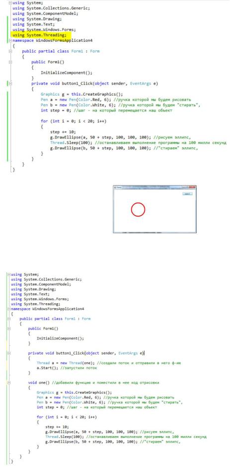
Результат работы программы:
Если мы во время анимации попробуем переместить окно по экрану или закрыть его, у нас не чего не получится. Причина этого в том, что программа выполняется в один поток, который занят рисованием. Переделаем код следующим образом.
Теперь во время анимации окно можно перемещать по экрану или закрыть его.
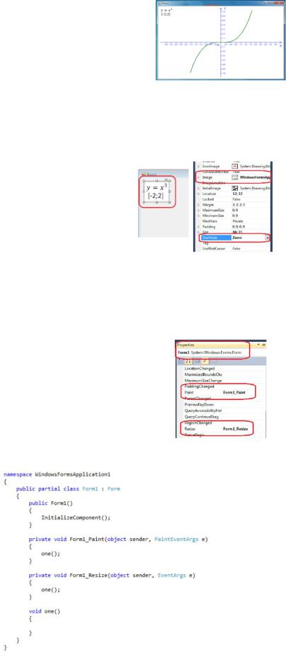
Построение графика функции
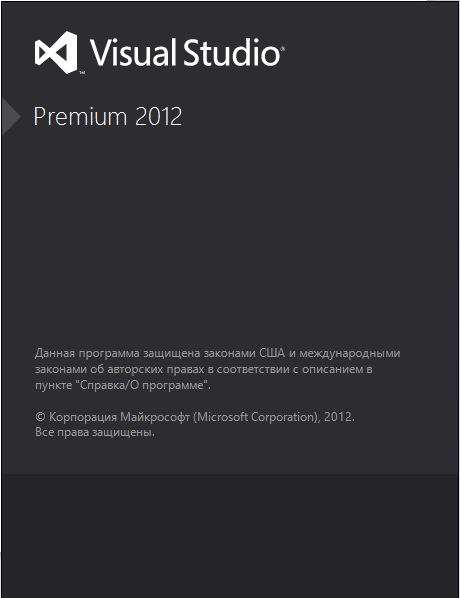
Построим график заданной функции, при изменении размера окна, график помещается в окне. В окне с функцией отобразим картинку с уравнением. Создадим новую форму и добавим на нее элемент pictureBox, в свойствах SizeMode -Zoom, Image – укажем картинку с формулой. (Картинку можно создать в Word’e (вставка->формула), а затем сделатьскриншот , сохранить и вставить сюда).
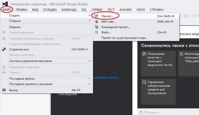
Далее заходим в события формы и два раза кликаем по событиям Paint и Resize, в итоге у нас создадутся две функции, третью – one(); мы создадим сами (в ней будем рисовать), и будем вызывать ее из двух других. Функция Paint выполняется при первоначальной отрисовке окна, Resize – при изменении размера окна.
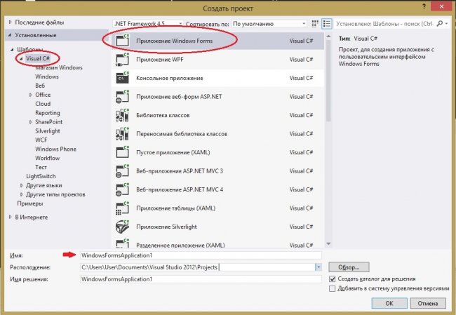
Вид файла Form1.cs

Добавляем в функцию one() код для создания необходимых для рисования Инструментов
Добавляем код для рисования и подписи осей
Далее рассчитаем значение функции на заданном интервале, и построим по этим значениям график.
Соседние файлы в предмете [НЕСОРТИРОВАННОЕ]
- #
- #
- #
- #
- #
- #
- #
- #
- #
- #
- #
“
В этом уроке поговорим о том, как можно визуализировать информацию с помощью графиков. Для этого будем использовать приложение WPF и элементы Windows Forms.
Для успешного освоения материала рекомендуем вам изучить следующие понятия:
DB (Database), БД. Организованная структура, предназначенная для хранения, изменения и обработки взаимосвязанной информации, преимущественно больших объемов
Framework. Программная платформа, определяющая структуру программной системы; программное обеспечение, облегчающее разработку и объединение разных компонентов большого программного проекта
Windows Presentation Foundation. Аналог WinForms, система для построения клиентских приложений Windows с визуально привлекательными возможностями взаимодействия с пользователем, графическая (презентационная) подсистема в составе .NET Framework (начиная с версии 3.0), использующая язык XAML
Демонстрация работы с графиками в Windows Forms
На данном занятии будет разработано простое приложение Windows Forms для визуализации расходов пользователей. Пользователи распределяют затраты по разным категориям и хранят их в общей базе данных. Итогом работы приложения будет служить работающая форма, в которой для каждого пользователя можно построить диаграммы различных типов для визуализации их расходов по категориям. Основные шаги построения приложения:
- Разработка интерфейса приложения
- Настройка взаимодействия с базой данных
- Реализация обработки данных

Важно
В рамках примера используется готовая база данных с информацией о пользователях, их платежах и категориях расходов
Разработка интерфейса приложения
1. Устанавливаем структуру формы

Важно
Интерфейс приложения будет состоять из двух основных частей: области построения и области настройки параметров просмотра
2. Добавляем элементы настройки параметров просмотра

Важно
Элементами настройки параметров просмотра будут являться выпадающие списки, позволяющие выбрать пользователя и тип диаграммы
3. Подключаем библиотеки для просмотра диаграмм

Важно
Диаграмма будет визуализироваться с помощью элемента Chart из WindowsForms. Воспользоваться данным элементом можно после подключения библиотеки System.Windows.Forms.DataVisualization, расположенного во вкладке Assemblies (сборки)
4. Добавляем элементы управления диаграммой

Важно
Диаграмма будет располагаться внутри элемента WindowsFormsHost. Данный элемент добавляется из окна ToolBox простым перетаскиванием
5. Добавляем пространство имен для работы с элементом Chart

6. Добавляем дополнительные параметры просмотра

Важно
Дополнительными параметрами являются имя диаграммы, а также легенда
Настройка взаимодействия с базой данных
1. Реализуем взаимодействие с базой данных

Важно
Взаимодействие реализуется путем добавления элемента «ADO.NET Entity Data Model»
2. Настраиваем свойства подключения базы данных

3. Добавляем подключение к базе данных

Реализация обработки данных
1. Создаем область построения графиков

Важно
Сперва создается поле для контекста EntityFramework с инициализацией. Затем создается область построения диаграммы ChartArea и добавляется в соответствующую коллекцию в конструкторе MainWindow
2. Добавляем наборы данных

Важно
Для каждого набора данных (например, данные линии на графике) необходимо добавлять в коллекцию Series. В данном случае есть одна серия данных для отображения сумм платежей по категориям. Объект Series создается с указанием названия и необходимости отображения на диаграмме
3. Загружаем данные из базы

Важно
Данные о пользователях загружаются в выпадающий список. Также загружаются типы диаграммы из перечисления SeriesChartType
4. Реализуем адаптивное изменение интерфейса

Важно
При выборе другого значения в ComboBox будет вызываться метод UpdateChart()
5. Получаем выбранные значения в выпадающих списках

Важно
Значения получаются как currentUser и currentType
6. Обрабатываем данные диаграммы

Важно
Приведенный код описывает получение серии данных диаграммы из соответствующей коллекции Series, установку типа диаграммы и очистку предыдущих данных
7. Обрабатываем список категорий

Важно
Список категорий получается из базы данных. Далее, в цикле foreach для каждой категории значение точки диаграммы добавляется в Points. Координата X будет названием категории, а координата Y будет суммой платежа для выбранного пользователя в текущей категории
Результат работы программы

“
Вы познакомились с тем, как использовать основные элементы Windows Forms в приложении WPF. Теперь давайте перейдем от теории к практике!
Для закрепления полученных знаний пройдите тест
Для взаимодействия с базами данных используется технология
Для размещение элемента управления Windows Forms на странице WPF используется
WindowsFormsIntegration является
К сожалению, вы ответили неправильно
Прочитайте лекцию и посмотрите видео еще раз
Но можно лучше. Прочитайте лекцию и посмотрите видео еще раз
Вы отлично справились. Теперь можете ознакомиться с другими компетенциями
Запустите Microsoft Visual Studio. Данный урок построен на базе версии 2012 года. Алгоритм работы с графикой аналогичен и для других версий.
Чтобы создать новый проект зайдите в меню «ФАЙЛ» в левом верхнем углу и выберите «Создать» -> «Проект» (или комбинацией клавиш Ctrl + Shift + N)как показано на рисунке.
В появившемся окне выберите из предложенных создаваемых объектов — Приложение Windows Forms для Visual C#.
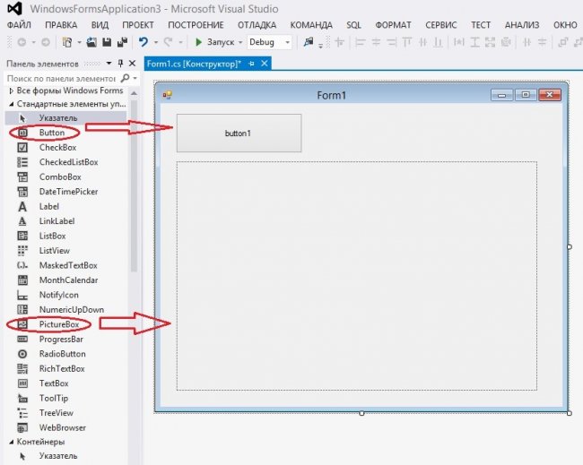
После создания проекта у вас на экране появится Форма (Form1) и Панель Элементов. Выберите их этой панели объекты:
- Button — кнопка,
- PictureBox — поле для рисования,
и расположите эти объекты на созданной ранее форме.
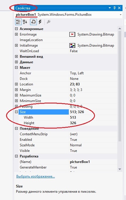
Выбрав на форме объект PictureBox, на панели «Свойства» вы можете настроить его характеристики. Например: Во вкладке «Макет» -> «Size» вы можете указать точный размер объекта в пикселях.
- Width — ширина по X ;
- Height — высота по Y ;
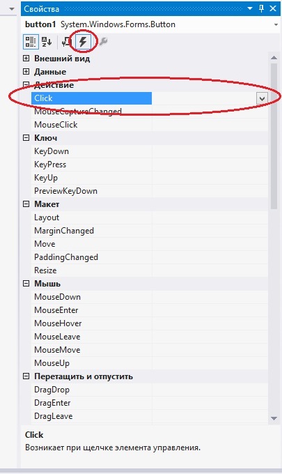
Выберите на своей форме объект Button1. В окне «Свойства» найдите кнопку «События» , во вкладке «Действие» напротив «Click» выберите название метода, отвечающего за событие при нажатии на кнопку.
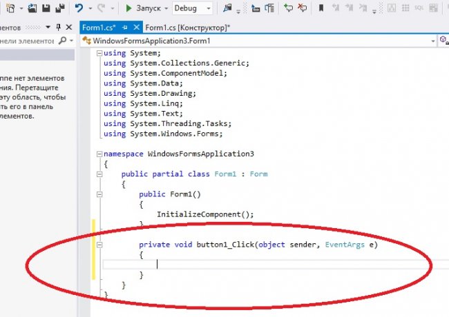
В файле Form1.cs будет создан метод, и будет представлять из себя:
private void button1_Click(object sender, EventArgs e)
        {

        }
Между фигурными скобками «{ }» необходимо написать код, который будет выполняться на событие клика по кнопке.
В языке C# существует целая библиотека для создания графики «System.Drawing». Она автоматически подключается при создании проекта.
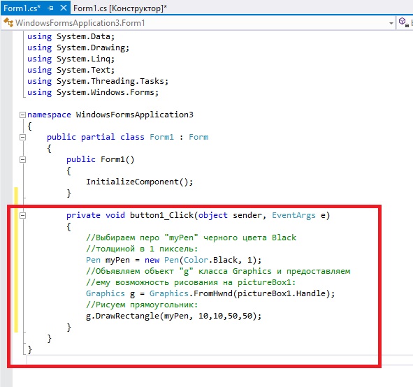
Например, можно нарисовать прямоугольник следующим образом:
       private void button1_Click(object sender, EventArgs e)
        {
            //Выбираем перо "myPen" черного цвета Black
            //толщиной в 1 пиксель:
            Pen myPen = new Pen(Color.Black, 1);
            //Объявляем объект "g" класса Graphics и предоставляем
            //ему возможность рисования на pictureBox1:
            Graphics g = Graphics.FromHwnd(pictureBox1.Handle);
            //Рисуем прямоугольник:
            g.DrawRectangle(myPen, 10,10,50,50);
        }
и файл Form1.cs будет иметь вид:
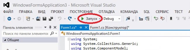
Чтобы запустить Проект нужно нажать на кнопку «Запуск» в виде зеленого треугольника на панели действий, или использовать «горячую клавишу» F5.
В конечном итоге у нас получится: